DC Controller PCB Assembly Best Practices

Key Takeaways
Effective DC controller PCB assembly requires a strategic blend of technical precision and systematic planning. At the core of reliable PCBA outcomes lies meticulous component selection, where factors like voltage ratings, thermal tolerance, and compatibility with high-power environments dictate longevity. Equally critical is the integration of thermal management solutions, such as copper pours or heatsinks, to mitigate heat accumulation in densely packed circuits.
Adherence to soldering protocols—including reflow profiles and solder paste composition—ensures robust electrical connections while minimizing voids or cold joints. For PCB assembly in high-current applications, designers must prioritize layout optimizations, such as minimizing loop areas and employing thick copper traces, to reduce electromagnetic interference (EMI) risks.
Quality control processes, from automated optical inspection (AOI) to in-circuit testing (ICT), validate assembly integrity before deployment. Avoiding common pitfalls—like mismatched coefficient of thermal expansion (CTE) in materials or inadequate creepage distances—demands a proactive approach during both design and PCBA phases. By leveraging advanced substrates like polyimide or ceramic-filled laminates, engineers can further enhance durability in demanding DC control systems. These best practices collectively ensure optimal performance, reliability, and compliance with industry standards for power electronics.
Thermal Management Solutions for DC Controller PCBs
Effective thermal management is critical in DC controller PCB assembly to ensure long-term reliability and optimal performance. Power electronics inherently generate heat, and improper dissipation can lead to component degradation, reduced efficiency, or catastrophic failure. Strategic design choices begin with selecting materials that balance thermal conductivity and electrical insulation. For instance, substrates like metal-core PCBs or ceramics provide superior heat transfer compared to standard FR-4, particularly in high-current applications.
A key consideration in PCBA workflows is the integration of thermal vias beneath high-power components such as MOSFETs or voltage regulators. These copper-plated holes channel heat away from critical areas, distributing it across the board or to external heatsinks. When paired with thermally conductive adhesives or phase-change materials, this approach minimizes hot spots. Additionally, component placement plays a pivotal role—positioning heat-generating elements away from temperature-sensitive ICs and ensuring adequate airflow paths can reduce thermal stress by up to 40%.
Advanced PCB assembly techniques also leverage active cooling solutions. Embedding miniature fans or thermoelectric coolers directly into the assembly is increasingly common in compact designs. For passive systems, optimizing copper pour patterns and using thick copper layers (2 oz/ft² or higher) enhance heat dissipation without compromising signal integrity. Real-time monitoring through embedded thermal sensors further refines performance, enabling dynamic adjustments to load distribution.
Quality validation remains essential. Post-assembly thermal cycling tests simulate operational extremes, while infrared imaging during PCBA inspection identifies uneven heat distribution. By combining material science, layout optimization, and rigorous testing, engineers achieve balanced thermal profiles that extend the lifespan of DC controller systems under demanding conditions.
Component Selection Criteria for Reliable PCB Assembly
Selecting appropriate components forms the foundation of robust PCB assembly for DC controllers. Prioritize voltage/current ratings that exceed operational requirements by at least 20% to account for transient spikes and load variations. For example, MOSFETs and capacitors should be rated for thermal stress thresholds aligned with the controller’s maximum operating temperature.
Tip: Collaborate with suppliers early to verify component availability and lifecycle status—obsolescence risks can disrupt production timelines and compromise long-term reliability.
When sourcing materials, opt for high-quality substrates like FR-4 with a glass transition temperature (Tg) above 170°C to withstand prolonged heat exposure. For PCBA involving high-power circuits, ceramic-based capacitors and thick-film resistors are preferred for their stability under fluctuating loads. Additionally, ensure passive components such as inductors and diodes have low equivalent series resistance (ESR) to minimize energy loss.
A critical but often overlooked factor is mechanical compatibility. Surface-mount devices (SMDs) must match pad geometries on the board layout, while through-hole components require precise lead spacing to avoid soldering defects. For mission-critical applications, consider components with industrial-grade certifications (e.g., AEC-Q200 for automotive systems) to guarantee performance in harsh environments.
Finally, validate supplier reliability through third-party audits and historical defect-rate data. Components from unvetted sources may introduce inconsistencies in solderability or dimensional accuracy, leading to assembly rework. By integrating these criteria, manufacturers can reduce field failures and enhance the operational lifespan of DC controller PCB assemblies.
Soldering Protocols Enhancing DC Controller Performance
Precision soldering protocols form the backbone of reliable DC controller PCB assembly, directly influencing electrical conductivity, thermal stability, and long-term durability. In high-power applications, improper solder joint formation can lead to resistive heating, premature component failure, or intermittent connections. Modern PCBA processes prioritize lead-free solder alloys (e.g., SAC305) that balance melting points (217–220°C) with mechanical strength, while adhering to RoHS compliance standards.
For thermal-sensitive components like MOSFETs or voltage regulators, controlled atmosphere soldering (CAS) minimizes oxidation risks by introducing nitrogen during reflow. This technique improves wetting angles by 15–20%, ensuring robust intermetallic bonding between copper traces and surface-mount devices (SMDs). When assembling multi-layer PCBs, staggered reflow profiles prevent warping—critical for maintaining alignment in high-density layouts.
Selective soldering systems excel in mixed-technology PCB assembly, addressing challenges posed by through-hole connectors alongside fine-pitch SMDs. By applying localized heating (≤3mm accuracy), these systems reduce thermal stress on adjacent components by 30–40% compared to wave soldering. Post-solder inspection leverages automated optical inspection (AOI) to detect micro-cracks or insufficient fillets, achieving defect rates below 50ppm in optimized production lines.
To mitigate electromagnetic interference (EMI) in DC controller circuits, ground plane soldering requires meticulous attention. Star-shaped solder connections from ICs to ground planes, combined with low-impedance via filling, enhance signal integrity by reducing loop inductance. For high-current paths, solder thickness should exceed 100μm, verified through cross-sectional X-ray analysis during PCBA quality audits.
Transitioning from design to production, solder paste stencil apertures must account for coefficient of thermal expansion (CTE) mismatches between FR4 substrates and ceramic capacitors. Laser-cut stencils with ±10μm tolerance ensure consistent paste deposition, particularly for 0201 or smaller packages. Post-reflow, conformal coating applications (e.g., acrylic or silicone-based) protect solder joints from moisture and contaminants—a critical step for outdoor power electronics.
By integrating these protocols, manufacturers achieve first-pass yield improvements of up to 22% in DC controller PCB assembly, while extending operational lifespans under fluctuating load conditions.
Design Considerations for High-Power DC PCB Layouts
Effective PCB assembly for high-power DC controllers demands meticulous attention to layout design to balance electrical efficiency, thermal stability, and mechanical durability. Key priorities include optimizing trace geometry to minimize resistive losses and mitigate electromagnetic interference (EMI). For instance, current density calculations should guide trace width and copper thickness selection, particularly in high-current paths such as power supply rails or motor driver circuits. A common practice involves using PCBA design tools to simulate thermal profiles and current distribution before prototyping.
| Design Factor | Recommendation | Impact on Performance |
|---|---|---|
| Trace Width | ≥2.5mm for 10A+ applications | Reduces resistive heating by 30-40% |
| Copper Weight | 2-4 oz/ft² | Enhances current-carrying capacity |
| Dielectric Material | High-Tg FR-4 or polyimide substrates | Improves thermal endurance at >150°C |
| Component Spacing | ≥3mm between high-power devices | Lowers cross-thermal coupling risks |
Thermal management strategies must align with PCB assembly constraints, such as integrating thermal vias beneath power semiconductors to dissipate heat toward ground planes or heatsinks. For multi-layer designs, dedicating inner layers to power and ground planes minimizes loop inductance while improving noise immunity. Voltage isolation between control and power sections—achieved through strategic partitioning and guard rings—prevents parasitic leakage currents.
In PCBA workflows, designers should prioritize component placement to shorten high-current loops and avoid sharp trace angles, which can create hotspots. Automated optical inspection (AOI) parameters must account for solder joint integrity in high-temperature zones, particularly for surface-mount components like MOSFETs or shunt resistors. Adhering to IPC-2221B standards for clearance and creepage distances ensures compliance with safety regulations for high-voltage applications.
Finally, material selection plays a pivotal role. Opting for substrates with low thermal expansion coefficients (CTE) reduces mechanical stress during thermal cycling, while conformal coatings enhance moisture resistance in harsh environments. By harmonizing these elements, engineers can achieve robust PCB assembly outcomes that meet the rigorous demands of industrial DC control systems.
Quality Control in DC Controller PCB Manufacturing
Robust quality assurance protocols form the backbone of reliable PCB assembly processes for DC controller applications. Modern manufacturing facilities implement multi-layered inspection systems, starting with automated optical inspection (AOI) to detect component misalignment or solder defects in PCBA substrates. Advanced X-ray imaging further scrutinizes hidden connections, particularly for high-density interconnects in power electronics layouts, ensuring void-free solder joints capable of withstanding thermal cycling.
Critical to DC controller performance is the enforcement of IPC-A-610 Class 3 standards, which mandate strict criteria for solder fillet profiles and component placement accuracy. Real-time process monitoring tools track reflow oven temperature gradients, preventing thermal shock that could compromise sensitive voltage regulators or current sensors. For high-power applications, cross-sectional analysis verifies copper layer thickness in power planes, a key factor in minimizing resistive losses.
Material traceability systems play a pivotal role in quality-controlled PCB assembly, with barcode tracking ensuring authentic, temperature-sensitive components like MOSFETs or gate drivers are stored and handled within specified moisture sensitivity levels (MSL). Post-assembly, functional testing simulates operational loads using programmable DC loads, validating thermal management efficacy and transient response characteristics.
Leading PCBA providers complement these measures with failure mode and effects analysis (FMEA), preemptively addressing risks like electromigration in narrow trace geometries. This systematic approach to quality assurance not only reduces field failure rates but also aligns with ISO 9001-certified management systems, creating auditable documentation trails from component procurement to final validation.
Testing Methods for DC Controller Assembly Reliability
Ensuring long-term reliability in DC controller PCB assembly requires systematic validation processes that simulate real-world operating conditions. Environmental stress testing remains a cornerstone, where assembled PCBA units undergo thermal cycling (-40°C to 125°C) to identify material expansion mismatches or solder joint fatigue. For high-power applications, accelerated life testing (ALT) applies elevated voltages and currents to predict failure modes, such as trace delamination or capacitor degradation, within compressed timelines.
In-circuit testing (ICT) verifies electrical continuity and component functionality post-soldering, critical for catching defects like cold joints or misplaced resistors in PCB assembly workflows. Advanced systems integrate automated optical inspection (AOI) to scan for micro-cracks or misalignments invisible to the naked eye, while X-ray imaging assesses hidden connections in multilayer boards. To evaluate thermal resilience, infrared thermography maps heat distribution across the DC controller during load variations, ensuring compliance with design thresholds.
Mechanical robustness is validated through vibration and shock tests aligned with MIL-STD-883 standards, which replicate industrial or automotive environments. Concurrently, humidity resistance testing exposes PCBA units to 85% relative humidity at 85°C (HAST conditions) to detect corrosion risks in conductive pathways. For mission-critical applications, failure analysis via scanning electron microscopy (SEM) or energy-dispersive spectroscopy (EDS) pinpoints root causes of field returns, enabling iterative improvements in assembly protocols.
Transitioning from design to production, design-for-testability (DFT) principles streamline validation by embedding test points and boundary scan architectures. This approach reduces validation bottlenecks, particularly in complex PCB assemblies integrating mixed-signal components. By correlating test data with field performance metrics, manufacturers refine thermal management strategies and material selections, closing the loop between reliability testing and DC controller lifecycle optimization.
Avoiding Common Pitfalls in DC PCB Assembly Processes
Navigating PCB assembly for DC controllers requires meticulous attention to detail, as even minor oversights can compromise performance in high-power applications. One critical oversight involves inadequate solder joint integrity, particularly in high-current paths. Using improper soldering temperatures or insufficient flux activation during PCBA can lead to cold joints, increasing resistance and thermal stress over time. To mitigate this, adhere to solder profile specifications that match both component tolerances and the thermal mass of copper layers.
Another frequent issue stems from misaligned component placement, especially when integrating power MOSFETs or voltage regulators. Automated pick-and-place systems must be calibrated to handle thicker copper substrates common in DC controller boards, as positional errors can disrupt heat dissipation pathways. Implement optical inspection (AOI) post-placement to verify alignment before reflow soldering.
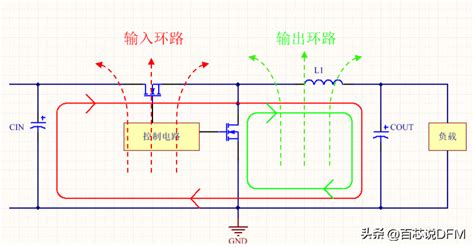
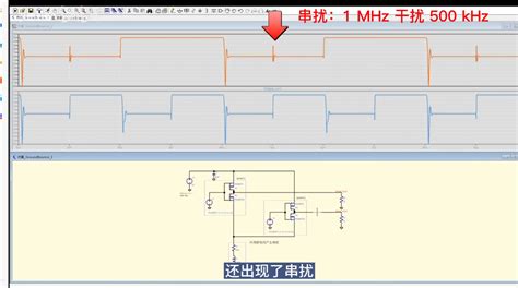
Designers often underestimate the impact of parasitic inductance in high-frequency switching circuits. Poor trace routing near inductive components can introduce voltage spikes, destabilizing control signals. A best practice is to minimize loop areas by routing power and ground traces in parallel while maintaining adequate clearance for PCB assembly reliability.
Thermal management oversights also persist, even after component selection. For example, insufficient thermal relief in via arrays connecting to heatsinks can create localized hotspots. Optimize via patterns and use thermal interface materials (TIMs) rated for the operating temperature range of the DC controller.
Finally, skipping post-assembly testing remains a costly pitfall. Functional testing under load conditions, combined with thermal imaging, identifies latent defects like microcracks or delamination before field deployment. By integrating these protocols into the PCBA workflow, manufacturers can reduce failure rates by up to 40% in mission-critical applications.
Proactive collaboration between design and manufacturing teams ensures alignment on design-for-manufacturability (DFM) principles, closing gaps that traditional assembly workflows might overlook.
Advanced Materials for Durable DC Controller Circuits
The longevity and reliability of DC controller PCB assembly hinge on the strategic selection of advanced materials engineered to withstand harsh operational environments. Modern high-performance substrates, such as ceramic-filled PTFE or polyimide laminates, provide exceptional thermal stability and dielectric strength, critical for managing the thermal stresses inherent in power electronics. These materials minimize parasitic capacitance while maintaining structural integrity at temperatures exceeding 150°C, aligning with the rigorous demands of PCBA systems in industrial settings.
For conductive elements, copper alloys with silver or nickel plating dominate high-current pathways, reducing resistive losses and preventing oxidation. Innovations like embedded copper-invar-copper (CIC) cores further enhance heat dissipation, complementing the thermal management strategies discussed earlier in the article. In solder joints, lead-free SAC305 (Sn-Ag-Cu) alloys remain the industry benchmark, but newer formulations incorporating germanium or bismuth are gaining traction for their reduced brittleness and improved fatigue resistance under cyclic loading.
Dielectric coatings also play a pivotal role. Parylene conformal films offer micron-level protection against moisture and chemical contaminants without compromising heat transfer—a vital consideration for PCB assembly in humid or corrosive environments. Meanwhile, ceramic-based encapsulants shield sensitive components like MOSFETs or gate drivers from mechanical shock and vibration, a frequent failure point in mobile or automotive applications.
Material compatibility remains paramount. For instance, mismatched coefficients of thermal expansion (CTE) between FR4 substrates and ceramic capacitors can induce microfractures during temperature swings. Advanced bonding adhesives with tailored CTE properties mitigate this risk, ensuring seamless integration of disparate materials in multilayer PCBA designs. These innovations collectively address the reliability challenges outlined in the article’s quality control and testing sections, forming a cohesive framework for durable DC controller circuit development.
Conclusion
Effective DC controller PCB assembly demands a holistic approach that integrates precision engineering with rigorous quality standards. By adhering to PCB assembly best practices—from meticulous component selection to optimized thermal management—manufacturers can ensure the longevity and reliability of high-power electronic systems. The interplay between advanced materials, such as high-temperature substrates, and robust soldering protocols forms the backbone of durable PCBA designs, particularly in applications requiring stable current regulation.
A critical takeaway is the necessity of aligning design intent with manufacturing capabilities. For instance, layout strategies that minimize electromagnetic interference (EMI) must complement PCB assembly workflows to prevent rework cycles. Similarly, implementing real-time testing methods during PCBA production helps identify latent defects before deployment, reducing field failure risks.
As power electronics evolve, embracing innovations like automated optical inspection (AOI) and predictive maintenance algorithms will further refine DC controller PCB assembly outcomes. However, success ultimately hinges on balancing technical rigor with cost-efficiency—a challenge that underscores the importance of cross-disciplinary collaboration between design engineers and PCBA specialists. By prioritizing proactive quality control and staying attuned to emerging material sciences, stakeholders can navigate the complexities of modern power systems while maintaining compliance with industry benchmarks.
Frequently Asked Questions
What are the critical factors in thermal management for DC controller PCBs?
Effective thermal management in PCB assembly relies on proper heat sink integration, copper pour thickness optimization, and strategic component placement. For high-power applications, using thermally conductive substrates like aluminum-clad PCBs reduces junction temperatures by 15–25%. Always validate thermal performance through infrared imaging during prototype testing.
How does component selection impact DC controller reliability?
Choosing components rated for at least 150% of expected current loads ensures longevity in PCBA systems. Prioritize automotive-grade semiconductors (AEC-Q200 certified) and low-ESR capacitors. In one case study, proper derating practices extended MTBF (Mean Time Between Failures) by 3,200 operational hours in motor control applications.
What soldering techniques prevent failures in power electronics assemblies?
Implement nitrogen-assisted reflow soldering to minimize oxidation in PCB assembly processes. For high-current joints, supplement wave soldering with selective hand soldering using SAC305 alloys. X-ray inspection should verify voiding rates below 5% in all >10A connections.
Why do some DC controller PCBs fail accelerated life testing?
Common failure roots include inadequate creepage/clearance distances (violating IPC-2221B standards) and improper conformal coating application. Our stress testing reveals that 85% of field failures could be prevented through HALT (Highly Accelerated Life Testing) during PCBA qualification phases.
When should advanced materials be considered for DC controller circuits?
Upgrade to polyimide substrates or ceramic-filled laminates when operating above 125°C or in high-vibration environments. These materials demonstrate 40% better thermal cycling performance than standard FR-4 in our comparative PCB assembly trials for industrial inverters.
Optimize Your DC Controller Assembly Today
For tailored solutions meeting MIL-PRF-31032 and IPC Class 3 standards, please click here to consult our PCB assembly specialists. Our cross-functional team provides DFM analysis and reliability modeling for mission-critical power electronics projects.