Detailed explanation of decoupling capacitor PCB design and layout
Today I will share with you: decoupling capacitor, decoupling capacitor PCB design and layout.
1.Decoupling capacitor
Decoupling capacitor is used to filter out the interference of output signal. It is usually used in amplifier circuits that do not require AC power to eliminate self-excitation and make the amplifier work at a low temperature.
In a circuit with only one conductor, when the power supply is shared, if there is a device that needs to provide output, the voltage of the conductor is pulled down at the same time, thereby generating noise coupled to the shared circuit.
In a noisy environment, electromagnetic waves will induce voltage signals in the conductor, affecting the components in the loop, and in digital circuits, due to interference at key positions, the device is prone to generate erroneous signals, causing erroneous actions.
Decoupling capacitors can reduce the above situation. Decoupling capacitors are generally placed at the power supply of components to reduce the influence of wiring impedance on the filtering effect. Most decoupling capacitors are ceramic capacitors, and their value is determined by the fastest rise and fall speed of the voltage signal.

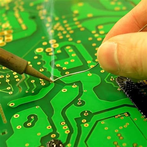
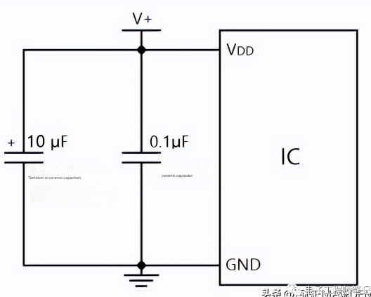
Typical application of using decoupling capacitors next to IC
2. The role of decoupling capacitors
(1)Removing high frequency
Decoupling capacitors are mainly used to remove high-frequency interference such as radio frequency signals that enter the device through electromagnetic radiation. The capacitors near the chip also store energy. Assuming that the main power supply is a reservoir, every household in our building needs water supply, and the water does not come directly from the reservoir because it is too far away and takes a long time. In fact, the water comes from the water tower stored nearby, which can play a buffering role. From a microscopic point of view, when high-frequency devices are working, their current is discontinuous, the frequency is very high, and there is a certain distance between the device VCC and the main power supply. At high frequency, the impedance Z is:

Impedance and the inductance of the line will also be very large, and the equipment cannot be powered in time. Decoupling capacitors can make up for this deficiency, which is one of the reasons why many small capacitors are placed on the VCC pins of high-frequency devices on PCB boards.
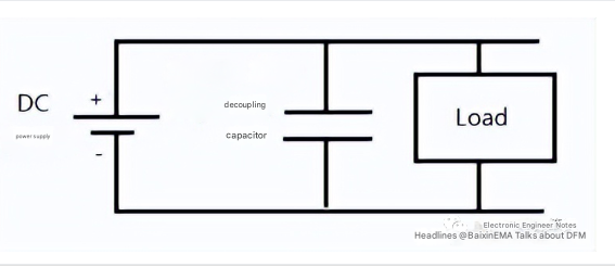
(2)Provide DC power to active devices
When active devices are turned on and off, high-frequency noise is generated and transmitted along the power line. The main function of decoupling capacitors is to provide local DC power to active devices to reduce the propagation of switching noise on the PCB board and lead the noise to the ground.
3.Decoupling capacitor calculation
The original purpose of decoupling: keep the voltage limit within the specified allowable error regardless of the requirements of regulations and current fluctuations.
(1)Calculation method 1
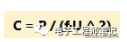
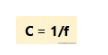
The capacitance value C of the decoupling capacitor required by the IC can be calculated by the following formula:

Decoupling capacitor capacitance
⊿U is the allowable reduction in the actual power bus voltage (V);
I is the maximum required current (A);
⊿t is the duration of the required capacitance.
2.Calculation method 2
It is recommended that the decoupling capacitor or value be greater than 1/m times the equivalent open-circuit capacitance. m is the maximum percentage of power bus voltage variation allowed on the IC power pin, which is usually given in the IC data sheet. The following is the equivalent open-circuit capacitance:
Equivalent open-circuit capacitance
P: Total wattage dissipated by the IC
U: Maximum DC supply voltage of the IC
f: Clock frequency of the IC
After determining the equivalent open-circuit capacitance, multiply it by 1/m to get the total decoupling capacitance or value required by the IC. Then divide the result by the total number of power pins connected to the same power bus, and finally get the capacitance value near all power pins connected to each power bus.
3.Selection and layout of PCB decoupling capacitors
The more decoupling capacitors, the better. Pay attention to the filtering effect. When designing the PCB, a 10uf-100uf electrolytic capacitor is connected across the power input end, and a 0.01μF ceramic capacitor is configured between the power supply and ground of each integrated chip.
On the one hand, the decoupling capacitor provides and absorbs the instantaneous charge and discharge energy when the integrated circuit is turned on and off, and on the other hand, it bypasses the high-frequency noise of the equipment.
4.Classification of decoupling capacitors
When the decoupling capacitor compensates the integrated chip or the PCB working voltage drops, it can play a role in energy storage. It can be divided into three types: integral type, local type and inter-board type.
1) Overall decoupling capacitor
The overall decoupling capacitor operates in the low-frequency (<1MHz) range, providing a current source for the entire PCB to compensate for the noise current ΔI generated by the PCB during operation and ensure the stability of the working power supply. The overall decoupling capacitor is 50 to 100 times the sum of all load capacitors on the PCB.
Generally speaking, the overall decoupling capacitor should be placed close to the power extension line and ground line of the PCB, and the printed wiring density is very high. It provides space for placing key printed circuits on the PCB without reducing low-frequency decoupling.
2) Local decoupling
There are two reasons for local decoupling: 1 is because of the function, 2 is because of the EMC aspect, as shown below:
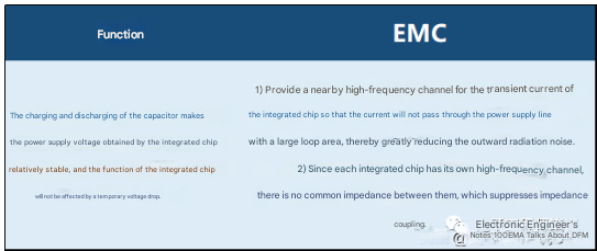
Reasons for local decoupling
The local decoupling capacitor is installed between the power terminal and the ground terminal of the integrated chip, and as close to the integrated chip as possible.
3) Inter-board decoupling capacitor S
Inter-board decoupling capacitor refers to the capacitance between the power layer and the ground layer, which is the main source of high-frequency decoupling current. The capacitance between the planes can be increased by increasing the area between the power layer and the ground layer.
In PCB, some planes can be distributed to the power plane. Removing these ground planes and replacing them with power isolation areas will increase the capacitance between the planes.
5.PCB decoupling capacitor value
In DC power supply circuits, changes in load will generate power supply noise. For example, in digital circuits, when the circuit switches from one state to another, a large peak current will be generated on the power line, forming a transient noise voltage.
Configuring decoupling capacitors can suppress the noise caused by load changes. This method is often used in PCB reliability design. A good high-frequency decoupling capacitor can remove high-frequency components up to 1GHz. Ceramic chip capacitors or multilayer ceramic capacitors have better high-frequency characteristics.
When designing PCBs, a decoupling capacitor must be added between the power supply and ground of each integrated circuit.
Decoupling capacitors have two functions. On the one hand, they are energy storage capacitors for integrated circuits, providing and absorbing instantaneous charge and discharge energy when the integrated circuit is turned on and off. On the other hand, decoupling capacitors bypass the high-frequency noise of the device.
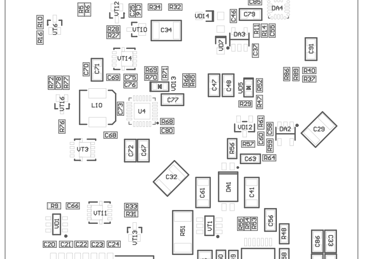
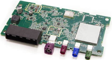
PCB decoupling capacitors
The configuration principles of decoupling capacitors are as follows:
1) Power supply configuration filter capacitors
A 10μF ~ 100μF electrolytic capacitor is connected across the power input. If the position of the PCB allows, the anti-interference effect of this electrolytic capacitor will be better. 1μF and 10μF capacitors with parallel resonant frequencies above 2020MHz are effective in removing high-frequency noise.
It is usually beneficial to apply capacitors in areas where the power supply enters the PCB, and battery-powered systems usually also need such capacitors.
2) Decoupling capacitors configured on chips
Each integrated circuit chip is configured with a 0.01μF ceramic capacitor. The typical decoupling capacitor in digital capacitors is 0.1/μF.
The decoupling capacitor has a distributed inductance of 5nH and a parallel resonant frequency of about 7MHz, which means that it has a good decoupling effect on noise below 10MHz and has little effect on noise above 40MHz.
If the space of the PCB is too small, a 1μF to 10μF tantalum electrolytic capacitor can be added for every 4 to 10 chips.
The high-frequency impedance of this capacitor is particularly small, less than 1μF-10μF in the range of 500kHz-20MHz, and the leakage current is very small (less than 0.5μA).
The selection of decoupling capacitors is not so strict, and can be calculated using the following formula:
Decoupling capacitors For systems composed of single-chip microcomputers, the capacitor can be between 0.1μF and 0.01μF.
3) Charge and discharge capacitor S
A charge and discharge capacitor with a capacity of 10uf is required for every 10 or so integrated circuits. The commonly used large capacitor is an electrolytic capacitor. However, when the filtering frequency is high, the electrolytic capacitor will roll up 2 layers of film, and the rolled-up structure behaves as an inductor at high frequencies.
In this case, use tantalum capacitors or polycarbonate capacitors.
6. Factors affecting PCB decoupling capacitor layout
(1)Influence of capacitor leads
When using capacitors to suppress electromagnetic interference and filter, the most easily overlooked problem is the influence of capacitor lead filtering effect.
The capacitive reactance of a capacitor is inversely proportional to the frequency. Based on this feature, a capacitor is connected in parallel between the signal line and the ground line to bypass high-frequency noise. However, in actual circuits, many people have found that this method does not achieve the expected noise filtering and effect. One of the reasons is that the influence of the capacitor lead on the bypass effect is ignored.
The actual capacitor type is a series network composed of equivalent series inductance (ESL), capacitor and equivalent series capacitance (ESR).
The impedance of an ideal capacitor decreases with the increase of frequency. The impedance characteristics of an actual capacitor are shown in the figure below:
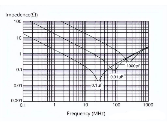
Impedance characteristics of actual capacitors
When the frequency is low, it exhibits the characteristics of a capacitor, that is, the impedance decreases with the increase of frequency. Resonance occurs at a certain point, and the impedance of the capacitor is equal to the ESR. Above the resonance, due to the effect of ESL, the impedance of the capacitor increases with the increase of frequency, making the capacitor exhibit the impedance characteristics of an inductor. As the impedance of the capacitor increases, the bypass effect on high-frequency noise weakens or even disappears.
Therefore, when arranging decoupling capacitors, pay attention to the influence of the distributed parameters of the capacitors on filtering.
(2)The role of capacitor leads
The resonant frequency of the capacitor is determined by ESL and C. The larger the capacitance or inductance, the lower the resonant frequency, which means that the high-frequency filtering effect of the capacitor is worse.
In addition to the type of capacitor, the length of the lead is also a very important parameter of ESL. The longer the lead, the greater the inductance, and the lower the resonant frequency of the capacitor.
Therefore, in actual design, the lead of the capacitor should be as short as possible. The correct and incorrect installation methods of the capacitor are shown in the figure below:
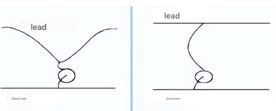
Installation method of filter capacitor
According to the principle of LC capacitor series resonance, the resonance point is not only related to the inductance, but also to the capacitance value. The larger the capacitance, the lower the resonance point.
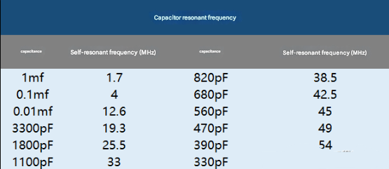
Some people think that the larger the capacitance, the better the filtering effect. This is a misunderstanding. Although the larger the capacitance, the better the bypass effect of low-frequency interference, the impedance begins to increase with the increase of frequency due to the low resonance frequency of the capacitor, and the bypass effect of high-frequency noise becomes worse. The self-resonant frequency of ceramic capacitors with different capacitances is given in the table, and the lead length of the capacitor is 1.6mm.
Although the resonance of the capacitor is not desirable from the perspective of filtering high-frequency noise, it also has a good side. When the frequency of the noise to be filtered is determined, the capacitor can be adjusted so that the resonance point just falls on the interference frequency.
(3)Influence of temperature
Temperature also has a great influence on the characteristics of the capacitor. Since the dielectric parameters in the capacitor are affected by temperature changes, the capacitance value of the capacitor also changes with temperature. Different dielectrics have different temperature change rules. The capacitance of some capacitors will drop by more than 70% when the temperature rises.
Commonly used filter capacitors are ceramic capacitors. Ceramic capacitors are divided into three types: ultra-stable, stable and general-purpose. The temperature characteristics of different dielectric capacitors are shown in the figure.
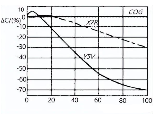
Temperature characteristics of different dielectric capacitors
It can be seen that the capacitance of COG capacitors hardly changes with temperature. The capacitance change of X7R capacitors within the rated operating temperature range is within 12%, and the capacitance change of YSV capacitors within the rated operating temperature range is more than 70%.
Temperature characteristics are what we should pay attention to, otherwise the performance of the filter will change at high or low temperatures, resulting in electromagnetic compatibility problems.
Although COG dielectric capacitors are less affected by temperature and have stable characteristics, their dielectric constant is low, generally 10 to 100, so when the volume is small, the capacitance will also be small.
The dielectric constant of XTR dielectric capacitors is much higher, from 2000 to 4000, so a smaller volume can produce a larger capacitance
YSV dielectric capacitors have the highest dielectric constant, 5000-25000, and are usually used in situations where a smaller volume and larger capacitance are required.
When selecting capacitors, many people unilaterally pursue small capacitors. Although this type of capacitor has a high dielectric constant, its temperature stability is very poor, which will lead to poor temperature characteristics of the device. This is something we should pay special attention to when selecting capacitors, especially military equipment.
(4)The influence of PCB voltage
The capacity of the capacitor changes not only with temperature, but also with the operating voltage. This must be noted in actual projects.
The figure below shows the voltage characteristics of capacitors with different dielectric materials.
In the figure, at the rated voltage, the capacity of the X7R capacitor is reduced to 70% of the original, and the capacity of the YSV capacitor is reduced to 30% of the original.
Therefore, when selecting capacitors, there should be a margin for voltage and capacitance values, otherwise the filter will not achieve the expected effect at the rated operating voltage. When the influence of temperature and voltage are considered at the same time, the change of capacitance is shown in the figure.
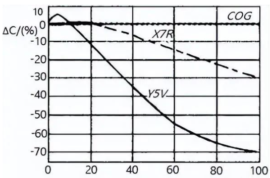
Voltage characteristics of capacitors Therefore, we must fully consider the filtering effect of capacitors when placing filter capacitors.
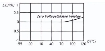
Temperature/voltage characteristics of capacitors
7.Reasonable placement of PCB decoupling capacitors
- Generally, only a few power decoupling capacitors are drawn in the schematic diagram, but it is not indicated where they should be connected. In fact, these capacitors are set for switching devices (gate circuits) or other components that need decoupling, so they should be placed as close to these components as possible. When the power decoupling capacitors are properly arranged, the grounding point problem is not so obvious.
- For devices with weak noise resistance, large current changes when power is off, and memory devices such as ROM and RAM, a decoupling capacitor should be directly connected between the chip power line (VCC) and the ground (GND).
- The lead of the decoupling capacitor should not be too long. The shorter the lead, the better the decoupling effect.In particular, high-frequency bypass capacitors cannot have leads.
- The amount of decoupling is not the more the better, but the filtering effect should be paid attention to, and the number and size of capacitors should be selected according to the time of the circuit board and the device.
- Ceramic capacitors and electrolytic capacitors have poor capacitance accuracy and large distributed inductance, and are not used when the decoupling requirements are high. Instead, tantalum capacitors or polyester capacitors should be used.
- In places where there are more chips and decoupling capacitors, charging and discharging capacitors can be installed to handle the charge generated when the circuit switches are working.