Electronic engineers often make these mistakes
Electronic Engineer refers to the senior engineers and technicians engaged in the research, teaching, product design, technology development, production and management of various electronic equipment and information systems. Generally divided into hardware engineers and software engineers.
Hardware Engineer: Mainly responsible for circuit analysis, design; and computer software as a tool for PCB design, factory PCB production is completed and the electronic components after welding test, commissioning;
Software Engineer: Mainly responsible for MCU, DSP, ARM, FPGA and other embedded programming and debugging. FPGA programs sometimes fall into the category of hardware engineers.
It is human beings who make mistakes, not to mention the engineers?
Although the twists and turns, engineers often make the same mistake! Here, you are invited to check in to see if they have the trick.
These pull high / low resistance with little resistance, little relationship, choose an integer 5K it.
Comment: There is no resistance of 5K on the market, the closest is 4.99K (accuracy 1%), followed by 5.1K (accuracy 5%), the cost of 4 times and 2 times higher than the 4.7K accuracy of 20% . 20% accuracy of the resistance value of only 1,1.5,2.2,3.3,4.7,6.8 several categories (including an integer multiple of 10); Similarly, 20% accuracy of the capacitor only the above values, if you choose the other Values must be used with higher precision, doubling the cost, but without any benefit.
This part of the circuit as long as the requirements of the software design will not be a problem.
Comments: Many of the electrical properties of the hardware directly under the control of the software, but the software is often an accident, after the program ran can not be expected to fly what the operation. The designer should make sure that no permanent damage should occur in a short period of time, regardless of what operating hardware the software is doing.
This logic with 74XX gate circuit ride is also OK, but too earth, or use CPLD, it seems more upscale.
Comments: 74XX gate circuit only a few cents, while the CPLD has at least dozens of pieces. N times the cost increase does not say, but also to the production, documentation and other work to add several times the work.
PCB board design requirements of this board is not high, it uses a little thin line, automatically cloth it.
Comments: Automatic routing is bound to take up a larger PCB area, while producing much better than the manual wiring through the hole, in a large number of products, PCB manufacturers cut prices factors considered in addition to business factors, is the line width and too The number of holes, respectively, affect the PCB yield and the number of drill consumption, saving the cost of the supplier, also gave a reason for price cuts.
Our system is 220V power supply, you do not have to care about the power problem.
Comments: Low-power design is not just for power saving, the more the benefits of reducing the cost of power modules and cooling systems, due to the current reduction also reduces the electromagnetic radiation and thermal noise interference. As the device temperature decreases, the device lifetime is extended accordingly (for every 10 degrees increase in the operating temperature of a semiconductor device, the lifetime is reduced by half)
These bus signals are pulled with a resistor, feel relieved.
Comments: The signal needs to be pulled up for many reasons, but not all have to pull. Pull the pull-down resistor pull a simple input signal, the current will dozens of microamps below, but pull a driven signal, the current will reach milliampere level, the current system is often 32-bit address data, there may be 244/245 bus and other signals isolated, are pulled up, then a few watts of power consumption on these resistance on (do not use the idea of eight cents for a few watts of power consumption).
CPU and FPGA I do not have these I / O port how to deal with it? Let it be empty, after that.
Comments: do not use the I / O port if left vacant, subject to a little bit of interference from the outside world may become the input signal of repeated oscillations, and the MOS device power consumption basically depends on the number of door flip. If you pull it up, each pin will have micro-level current, so the best way is to set the output (of course, can not be connected to the other outside the drive signal)
This FPGA has so many doors left to use, you can enjoy it.
Comments: The power consumption of FGPA is proportional to the number of flip-flops used and the number of flip-flops used, so the power consumption of the same type of FPGA may vary by 100 times at different times of different circuits. Minimizing the number of flip flops at high speed is the fundamental way to reduce FPGA power consumption.
The power consumption of these chips are very low, do not consider.
Comments: For the internal complexity of the chip is difficult to determine the power, which is mainly determined by the current on the pin, an ABT16244, no load, then the power consumption of less than about 1 mA, but its indicator is that each pin Can drive the load of 60 milliamperes (such as matching resistance of several tens of ohms), that is, the maximum power consumption of full load can reach 60 * 16 = 960mA, of course, only the power supply current is so big, the heat falls on the load.
There are so many memory control signals, I only need to use this board OE and WE signal on it, the chip select on the ground bar, so read out the data came much faster.
Comments: Most of the memory power consumption in the chip select effective (regardless of OE and WE) will be more than 100 times larger than the chip select invalid, so the use of CS to control the chip, and to meet other requirements May shorten the width of chip select pulse.
How are these signals overshoot? As long as they match well, they can be eliminated.
Comments: Except for a few specific signals (such as 100BASE-T, CML), there are overshoots, so long as they are not very large, they do not necessarily need to be matched, even though the match does not have to match the best. If TTL output impedance less than 50 ohms, and some even 20 ohms, if you also use such a large matching resistance, then the current is very large, the power consumption is unacceptable, the other signal amplitude will be too small to use, Besides the general output signal in the output high and output low impedance is not the same, but also to achieve an exact match. Therefore, TTL, LVDS, 422 and other signal matching as long as the overshoot can be accepted.
Reduce power consumption is a matter of hardware personnel, and software does not matter.
Comments: The hardware is only take a stage, singing is the software, almost every bus bus access, almost every signal flip control by the software, if the software can reduce the number of external memory access (more use of register variables, More use of internal CACHE, etc.), timely response to interrupts (interrupts tend to be active low with pull-up resistors), and other specific measures that compete for specific boards will make a significant contribution to reducing power consumption.
This clocked at 100M CPU can only handle 70%, 200M frequency on the right.
Comments: The system’s processing power involves a variety of factors, the bottleneck in the communications business are generally in memory, the CPU is fast, external access is not up fast in vain.
CACHE bigger CPU, it should be faster.
Comments: CACHE increases, does not necessarily lead to an increase in system performance, in some cases the closure of CACHE but faster than using CACHE. The reason is that data moved to CACHE must be repeatedly used to improve system efficiency. So in the communication system generally only open the command CACHE, data CACHE even open only part of the storage space, such as the stack part. CACHE also requires program design to take into account the capacity and size of the block, which involves the length of the key code loop body and the scope of the jump, if a cycle just a little more than CACHE big, but also in repeated cycles, then miserable.
However, a CPU processing, the two distribution processing, processing power can be doubled.
Comments: For moving bricks, two people should be twice as efficient as one person; for painting, more than one person can only help. Use a few CPUs to know more about the business before deciding to minimize the cost of coordinating the two CPUs so that 1 + 1 is as close as possible to 2 and not less than 1.
This CPU with a DMA module, use it to move the data is certainly fast.
Comments: The real DMA is preempted by the hardware bus at the same time start both ends of the device, read in one cycle here, there are some. However, a lot of DMA embedded in the CPU is just a simulation to start every DMA to do a lot of preparatory work (set the starting address and length, etc.), the transmission is often the first to read the chip temporarily stored, and then write out, That is to move a data two clock cycles, faster than the software to move (do not need to take instructions, there is no extra work such as looping), but if only a few bytes at a time, but also do a bunch of preparatory work, General also involves function calls, efficiency is not high. So this DMA only applies to big data blocks.
In order to ensure a clean power supply, it is much better to go even capacitor.
Comments: In general the more even the power to the power supply will be more stable, but too many disadvantages are also: a waste of costs, wiring difficulties, power surge current is too large. The key to the design of dual capacitors is to choose the right capacity and put on the place, the general chip manuals have competing for the design of the reference to the even capacitor, the best manual to do it.
Signal matching really troublesome, how to match it?
Comments: The signal reflection is caused by the uneven impedance of the line, the purpose of matching is to make the drive side, the load side and the transmission line impedance becomes close, but can match well, with the signal line on the PCB topology The structure is also very much related to the fact that a branch in the transmission line, a via hole, a corner, a connector, a change in the distance between the different locations and the ground line, etc., will change the impedance and these factors make the reflected waveform extremely complex , It is difficult to match, so high-speed signals only use the point-to-point approach, as much as possible to reduce the vias, corners and other issues.
User error can not blame me.
Comments: require users to operate strictly in accordance with the manual is not wrong, but the user is human, there are mistakes, we can not touch a key to crash, insert a plug on the burning board. Therefore, the user may make a variety of mistakes to be protected.
The reason for this bad board is the wrong side of the board, nor is it my responsibility.
Comments: For a variety of external hardware interface should be sufficient compatibility, not because the other signal is not normal, you rest. It should not affect only the part of its function, and other functions should work properly, should not strike completely, or even permanently damaged, and once the interface is restored, you should immediately return to normal.
Our system requirements so high, including MEM, CPU, FPGA and all other chips have to choose the fastest.
Comments: Not every part of a high-speed system is operating at a high speed, and every time the device speed increases by one level, the price almost doubled and the signal integrity problem is greatly adversely affected.
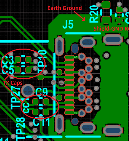
Finally, talk about small capacitor knowledge, but also engineers prone to make mistakes.
Why two capacitors in parallel:
First, the same type of capacitor parallel effect is mainly expansion;
Second is: Different types of capacitors in parallel is generally a strong sense, a weak sentiment.
Low-capacity high-frequency capacitive capacitor easy to pass, high-capacity capacitive
low-frequency signal easy to pass. Large capacitance at low frequencies can provide a good access, and at high frequencies due to the presence of parasitic inductance impedance will become larger and can not provide filtering path, so the high capacitance can not filter high frequency, while the small capacitance at low frequency impedance is too large Can not provide the filtering passway, so can not filter the high frequency and low frequency commonly with a capacitor.
The benefits of capacitors in parallel: is to increase the capacitance, reduce the capacitance. The more the parallel number, the more obvious the effect, but the higher the cost. Electrolysis is used to filter low frequency, ceramic is used to filter high frequency. In addition, electrolysis leakage current, so the back in the ceramic to eliminate leakage current.
In the switching power supply, the role of two capacitors in parallel for large capacitance filter is used, the small capacitor is used to eliminate large capacitance inductive characteristics of high frequency!
The role of capacitors (four common)
1, the filter effect: In the power circuit, the rectifier circuit will be AC into a pulsating DC, and access to the rectifier circuit after a larger capacity electrolytic capacitor, the use of its charge-discharge characteristics, so that the pulsating DC voltage into rectified Relatively stable DC voltage.
- Coupling: In the process of transmitting and amplifying low-frequency signals, capacitive coupling is often used to prevent the static operating points of the two circuits from interfering with each other.In order to prevent the loss of low frequency components in the signal, the total capacity Large electrolytic capacitor.
3, decoupling capacitor: and then connected to the power amplifier between the positive and negative, to prevent the positive resistance formed by the power supply caused by parasitic oscillations.
4, bypass capacitor: AC and DC signal in the circuit, the capacitor and then connected at both ends of the resistor or by a point across the circuit to a common potential for the AC signal or pulse signal to set a path to avoid the AC signal component Pressure drop attenuation through resistance.