Flex pcb guidelines
Design Best Practices Flex pcb guidelines
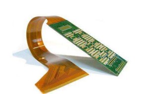
Designing flexible printed circuit boards (Flex PCBs) requires a meticulous approach to ensure reliability and functionality.
Flex PCBs offer numerous advantages, such as the ability to bend and fold, which makes them ideal for compact and complex electronic devices. However, their unique properties necessitate specific design considerations to avoid common pitfalls and optimize performance.
To begin with, material selection is paramount.
Flex PCBs are typically made from polyimide, a material known for its flexibility and thermal stability. Choosing the right thickness of the polyimide layer is crucial; it should be thick enough to provide mechanical support but thin enough to maintain flexibility. Additionally, the copper layer used for the conductive traces should be carefully selected. Rolled annealed (RA) copper is preferred over electro-deposited (ED) copper due to its superior flexibility and resistance to cracking.
Transitioning to the layout design, it is essential to consider the bend radius.
The bend radius is the minimum radius one can bend the flex PCB without causing damage. A general rule of thumb is to maintain a bend radius of at least ten times the thickness of the flex PCB. This precaution helps prevent stress fractures and ensures the longevity of the circuit. Moreover, designers should avoid placing vias and components in the bend areas, as these can be stress concentrators and lead to mechanical failure.
Another critical aspect is the trace routing.
Traces should be routed perpendicular to the bend lines rather than parallel. This orientation minimizes the stress on the traces during bending. Additionally, using curved traces instead of sharp angles can further reduce stress concentrations. It is also advisable to use wider traces and maintain consistent trace widths to enhance the mechanical robustness of the flex PCB.
Furthermore, the stack-up configuration plays a significant role in the performance of flex PCBs.
A balanced stack-up, where the copper layers are symmetrically placed around the core, helps maintain mechanical stability and prevents warping. In multi-layer flex PCBs, it is beneficial to use cross-hatching for the ground and power planes instead of solid fills. Cross-hatching reduces the overall stiffness and allows for better flexibility.
Transitioning to the topic of strain relief, it is important to incorporate features that mitigate mechanical stress.
Strain relief can be achieved by adding fillets to the corners of the flex PCB and using teardrop pads for vias and component leads. These features distribute stress more evenly and reduce the likelihood of cracking. Additionally, stiffeners can be used in areas that require additional mechanical support, such as connector interfaces.
Thermal management is another crucial consideration. Flex PCBs are often used in environments with varying temperatures, and excessive heat can degrade the materials and affect performance. To address this, designers should ensure adequate thermal dissipation by incorporating thermal vias and using materials with good thermal conductivity. It is also beneficial to perform thermal simulations during the design phase to identify potential hotspots and mitigate them accordingly.
In conclusion, designing flex PCBs requires a comprehensive understanding of their unique properties and challenges. By carefully selecting materials, optimizing layout design, considering stack-up configurations, incorporating strain relief features, and addressing thermal management, designers can create reliable and high-performance flex PCBs. These best practices not only enhance the mechanical and electrical performance of the flex PCBs but also extend their operational lifespan, making them a robust solution for modern electronic applications.
Material Selection For Flexible Circuit Boards
When designing flexible circuit boards, the selection of materials is a critical factor that significantly influences the performance, reliability, and cost-effectiveness of the final product. The unique properties of flexible circuit boards, such as their ability to bend, twist, and fold, necessitate careful consideration of the materials used in their construction.
The primary materials involved in the fabrication of flexible circuit boards include the substrate, conductive materials, adhesives, and protective coatings. Each of these components must be chosen with an understanding of their individual properties and how they interact within the overall assembly.
The substrate material forms the foundation of a flexible circuit board and is typically made from polyimide or polyester films.
Polyimide is favored for its excellent thermal stability, chemical resistance, and mechanical properties, making it suitable for high-temperature applications and environments where durability is paramount. Polyester, on the other hand, offers a cost-effective alternative with good flexibility and adequate performance for less demanding applications. The choice between polyimide and polyester substrates depends on the specific requirements of the application, including operating temperature, mechanical stress, and environmental conditions.
Conductive materials are another essential component of flexible circuit boards, with copper being the most commonly used due to its excellent electrical conductivity and ductility.
Copper can be deposited onto the substrate using various methods, such as electroplating, electroless plating, or lamination of copper foil. The thickness of the copper layer must be carefully controlled to balance electrical performance with flexibility. Thicker copper layers provide lower electrical resistance but can reduce the flexibility of the circuit. Conversely, thinner copper layers enhance flexibility but may increase electrical resistance and reduce current-carrying capacity. Therefore, the selection of copper thickness should align with the electrical and mechanical requirements of the application.
Adhesives play a crucial role in bonding the various layers of a flexible circuit board together.
The choice of adhesive depends on factors such as the materials being bonded, the operating environment, and the mechanical stresses the circuit will encounter. Commonly used adhesives include acrylics, epoxies, and pressure-sensitive adhesives (PSAs). Acrylic adhesives offer good flexibility and chemical resistance, making them suitable for a wide range of applications. Epoxy adhesives provide strong bonds and excellent thermal stability but may be less flexible than acrylics. PSAs are easy to apply and rework but may not offer the same level of performance as acrylics or epoxies in demanding environments. The selection of adhesive must ensure reliable bonding without compromising the flexibility and performance of the circuit.
Protective coatings, such as solder masks and coverlays,
are applied to flexible circuit boards to protect the conductive traces from environmental factors, such as moisture, dust, and mechanical abrasion.
Solder masks are typically made from liquid photoimageable (LPI) materials or dry film resists, providing a durable protective layer that can withstand the rigors of soldering processes. Coverlays, often made from polyimide films with adhesive backing, offer additional mechanical protection and insulation. The choice between solder masks and coverlays depends on the specific protection requirements and the manufacturing processes involved.
In conclusion, the selection of materials for flexible circuit boards is a complex process that requires careful consideration of the application’s electrical, mechanical, and environmental demands. By understanding the properties and interactions of substrates, conductive materials, adhesives, and protective coatings, designers can create flexible circuit boards that meet the desired performance criteria while ensuring reliability and cost-effectiveness.

Common Mistakes To Avoid In Flex PCB Design
Designing flexible printed circuit boards (flex PCBs) requires meticulous attention to detail and a thorough understanding of the unique challenges they present. One common mistake in flex PCB design is neglecting to account for the mechanical stresses that the board will endure. Unlike rigid PCBs, flex PCBs are subject to bending, folding, and twisting, which can lead to mechanical failure if not properly addressed. To mitigate this risk, designers should incorporate appropriate bend radii and avoid placing components or vias in areas that will experience significant flexing.
Another frequent error is the improper selection of materials.
Flex PCBs require materials that can withstand repeated flexing without degrading. Polyimide is a popular choice due to its excellent thermal stability and flexibility. However, designers must also consider the adhesive materials used to bond the layers together, as these can impact the board’s overall flexibility and durability. Failing to choose the right materials can result in delamination or cracking, compromising the board’s functionality.
In addition to material selection, trace routing is a critical aspect of flex PCB design that is often mishandled.
Designers must ensure that traces are routed in a manner that minimizes stress. This involves avoiding sharp corners and instead using curved traces, which distribute stress more evenly. Furthermore, traces should be routed perpendicular to the bend lines rather than parallel, as this orientation reduces the likelihood of trace cracking. Overlooking these routing guidelines can lead to electrical failures and reduced board lifespan.
Thermal management is another area where designers frequently make mistakes.
Flex PCBs are often used in compact, high-density applications where heat dissipation can be a challenge. Inadequate thermal management can lead to overheating and subsequent failure of the board. To address this, designers should incorporate thermal vias, heat sinks, and other cooling mechanisms into their designs. Additionally, they should consider the thermal properties of the materials used and ensure that the board layout facilitates efficient heat dissipation.
Moreover, designers often underestimate the importance of proper stack-up configuration.
The stack-up determines the arrangement of conductive and insulating layers within the PCB, and an improper configuration can lead to signal integrity issues and mechanical failures. For instance, placing too many layers in a single flex section can make the board too rigid, defeating the purpose of using a flex PCB. Conversely, too few layers can result in insufficient electrical performance. Therefore, a balanced stack-up that meets both mechanical and electrical requirements is essential.
Another pitfall in flex PCB design is inadequate testing and validation.
Given the unique stresses and conditions that flex PCBs are subjected to, standard testing procedures for rigid PCBs may not be sufficient. Designers should implement rigorous testing protocols that simulate the actual operating conditions of the flex PCB, including repeated bending and flexing cycles. Failure to do so can result in undetected issues that manifest during the product’s operational life, leading to costly recalls and repairs.
Lastly, poor communication with the manufacturer can lead to design flaws.
Flex PCBs have specific manufacturing constraints that must be considered during the design phase. Designers should work closely with their manufacturers to understand these constraints and ensure that their designs are manufacturable. This collaboration can help identify potential issues early in the design process, reducing the likelihood of costly revisions and production delays.
In conclusion, avoiding these common mistakes in flex PCB design requires a comprehensive understanding of the unique challenges posed by flexible circuits. By paying careful attention to mechanical stresses, material selection, trace routing, thermal management, stack-up configuration, testing, and manufacturer communication, designers can create robust and reliable flex PCBs that meet the demands of their applications.
Cost-Effective Manufacturing Tips For Flex PCBs
Flex PCBs, or flexible printed circuit boards, have become increasingly popular in various industries due to their versatility, lightweight nature, and ability to conform to complex shapes. However, manufacturing these intricate components can be costly if not approached with careful planning and strategic decision-making. To ensure cost-effective production, several guidelines should be followed, each contributing to the overall efficiency and affordability of the manufacturing process.
One of the primary considerations in cost-effective flex PCB manufacturing is the selection of materials.
Choosing the right substrate, such as polyimide, which offers excellent thermal stability and flexibility, can significantly impact both performance and cost. While high-quality materials may have a higher initial cost, they often result in fewer defects and longer-lasting products, ultimately reducing long-term expenses. Additionally, opting for standard material thicknesses and sizes can help minimize waste and lower material costs.
Design optimization is another crucial factor in reducing manufacturing costs.
Simplifying the design by minimizing the number of layers and using standard shapes can lead to more efficient production processes. For instance, reducing the number of vias and traces can decrease the complexity of the PCB, making it easier and faster to manufacture. Employing design for manufacturability (DFM) principles ensures that the design is tailored for efficient production, thereby reducing the likelihood of errors and rework.
Furthermore, panelization plays a significant role in cost-effective flex PCB manufacturing.
By arranging multiple PCBs on a single panel, manufacturers can maximize the use of materials and reduce production time. This approach not only minimizes waste but also allows for more efficient use of equipment and labor. Careful consideration of the panel layout, including the spacing between individual PCBs and the use of breakaway tabs, can further enhance manufacturing efficiency.
Another important aspect to consider is the choice of manufacturing processes.
Utilizing automated processes, such as automated optical inspection (AOI) and automated assembly, can significantly reduce labor costs and improve production speed. Automation also enhances precision and consistency, leading to higher-quality products with fewer defects. Additionally, selecting the appropriate soldering techniques, such as reflow soldering or wave soldering, based on the specific requirements of the flex PCB, can optimize production efficiency and reduce costs.
Supplier selection is equally critical in achieving cost-effective flex PCB manufacturing.
Partnering with experienced and reliable suppliers who offer competitive pricing and consistent quality can make a substantial difference. Establishing long-term relationships with suppliers can lead to better pricing agreements and more favorable terms. Moreover, working closely with suppliers during the design and prototyping stages can help identify potential cost-saving opportunities and streamline the production process.
Lastly, thorough testing and quality control are essential to ensure that the final product meets the required standards and specifications.
Implementing rigorous testing procedures, such as electrical testing and thermal cycling, can identify defects early in the production process, reducing the need for costly rework and ensuring that only high-quality products reach the market. Investing in quality control measures may incur additional upfront costs, but it ultimately leads to significant savings by preventing defective products from reaching customers.
In conclusion, cost-effective manufacturing of flex PCBs requires a comprehensive approach that encompasses material selection, design optimization, panelization, process automation, supplier collaboration, and stringent quality control. By adhering to these guidelines, manufacturers can achieve efficient production processes, reduce costs, and deliver high-quality flex PCBs that meet the demands of various applications.


