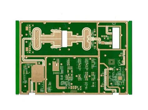
Flex pcb limitations
Material Constraints in Flex PCB Design
Flex PCBs, or flexible printed circuit boards, have revolutionized the electronics industry by offering unparalleled design flexibility and the ability to fit into compact and irregularly shaped spaces. However, despite their numerous advantages, flex PCBs come with a set of material constraints that designers must carefully consider to ensure optimal performance and reliability. Understanding these limitations is crucial for making informed decisions during the design and manufacturing processes.
One of the primary material constraints in flex PCB design is the choice of substrate.
Unlike rigid PCBs, which typically use FR-4 material, flex PCBs often employ polyimide or polyester films. Polyimide is favored for its excellent thermal stability, chemical resistance, and mechanical properties. However, it is also more expensive than traditional FR-4 materials, which can significantly impact the overall cost of the project. Polyester, while more cost-effective, does not offer the same level of thermal and mechanical performance, making it less suitable for high-temperature or high-stress applications.
Another critical material constraint is the type of adhesive used in the construction of flex PCBs.
Adhesives are essential for bonding the various layers of the PCB together, but they can also introduce potential weaknesses. For instance, some adhesives may not withstand high temperatures or harsh environmental conditions, leading to delamination or failure over time. Therefore, selecting an adhesive that matches the specific requirements of the application is vital. Additionally, the thickness of the adhesive layer can affect the overall flexibility and bend radius of the PCB, further complicating the design process.
The choice of conductive materials also presents limitations.
Copper is the most commonly used conductor in flex PCBs due to its excellent electrical properties. However, the thickness and type of copper foil can influence the board’s flexibility and durability. Thicker copper layers provide better current-carrying capacity but reduce flexibility, while thinner layers enhance flexibility but may not support high current loads. Moreover, the method of copper deposition, whether rolled annealed or electro-deposited, can impact the mechanical properties of the flex PCB. Rolled annealed copper offers better flexibility and fatigue resistance, making it more suitable for dynamic applications where the PCB will undergo repeated bending.
Furthermore, the protective coatings and surface finishes used in flex PCB design can impose additional constraints.
These coatings are essential for protecting the circuitry from environmental factors such as moisture, dust, and chemicals. However, they can also affect the board’s flexibility and overall performance. For example, some conformal coatings may add rigidity to the flex PCB, limiting its ability to bend and flex as required. Similarly, surface finishes like ENIG (Electroless Nickel Immersion Gold) or HASL (Hot Air Solder Leveling) can impact the board’s flexibility and solderability, necessitating careful selection based on the specific application needs.
In addition to these material constraints, designers must also consider the mechanical limitations imposed by the flex PCB’s intended use.
The bend radius, or the minimum radius the PCB can be bent without causing damage, is a critical factor. Exceeding the recommended bend radius can lead to cracks in the copper traces or delamination of the substrate, compromising the board’s functionality. Therefore, understanding the mechanical properties of the chosen materials and adhering to design guidelines is essential for ensuring the longevity and reliability of the flex PCB.
In conclusion, while flex PCBs offer significant advantages in terms of design flexibility and space-saving capabilities, they also come with a set of material constraints that must be carefully managed. By understanding the limitations associated with substrates, adhesives, conductive materials, protective coatings, and mechanical properties, designers can make informed decisions that optimize the performance and reliability of their flex PCB designs.
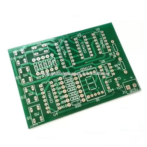
Thermal Management Challenges in Flex PCBs
Flex PCBs, or flexible printed circuit boards, have revolutionized the electronics industry by offering unparalleled design flexibility, reduced weight, and the ability to fit into compact spaces. However, despite their numerous advantages, flex PCBs are not without their challenges. One of the most significant issues faced by designers and engineers is thermal management. Effective thermal management is crucial for ensuring the reliability and longevity of electronic devices, and this becomes particularly complex in the context of flex PCBs.
To begin with, the materials used in flex PCBs inherently present thermal management challenges.
Unlike traditional rigid PCBs, which often use materials like FR4 that have relatively good thermal conductivity, flex PCBs are typically made from polyimide or polyester substrates. These materials are chosen for their flexibility and durability, but they have lower thermal conductivity compared to FR4. Consequently, heat dissipation becomes less efficient, leading to potential hotspots that can degrade the performance and reliability of the electronic components.
Moreover, the compact and often intricate designs of flex PCBs exacerbate thermal management issues.
The very nature of flex PCBs allows them to be bent, folded, and twisted to fit into tight spaces within electronic devices. While this is advantageous for miniaturization and design versatility, it also means that there is less surface area available for heat dissipation. In addition, the close proximity of components can lead to localized heating, further complicating thermal management efforts.
Another factor to consider is the thermal expansion properties of the materials used in flex PCBs.
Polyimide and polyester have different coefficients of thermal expansion compared to the copper traces and other metallic components on the board. This mismatch can lead to mechanical stresses during thermal cycling, potentially causing delamination, cracking, or other forms of mechanical failure. Therefore, careful consideration must be given to the thermal expansion properties of all materials used in the construction of flex PCBs to mitigate these risks.
Furthermore, the integration of high-power components in flex PCBs poses additional thermal management challenges.
As electronic devices become more powerful and compact, the demand for integrating high-power components such as processors, LEDs, and power transistors into flex PCBs increases. These components generate significant amounts of heat, which must be effectively managed to prevent thermal runaway and ensure stable operation. Traditional cooling methods, such as heat sinks and fans, are often impractical for flex PCBs due to their flexible nature and space constraints. As a result, alternative cooling solutions, such as thermal vias, heat spreaders, and advanced thermal interface materials, must be employed to manage the heat generated by these high-power components.
In addition to these material and design challenges, the manufacturing process of flex PCBs also impacts thermal management.
The lamination process used to bond the layers of a flex PCB can introduce thermal stresses, which may affect the board’s thermal performance. Moreover, the use of adhesives in the construction of flex PCBs can create thermal barriers that impede heat dissipation. Therefore, optimizing the manufacturing process to minimize thermal stresses and improve heat transfer is essential for effective thermal management in flex PCBs.
In conclusion, while flex PCBs offer numerous advantages in terms of design flexibility and miniaturization, they also present significant thermal management challenges. The materials used, the compact and intricate designs, the integration of high-power components, and the manufacturing process all contribute to the complexity of managing heat in flex PCBs. Addressing these challenges requires a comprehensive understanding of thermal properties, careful material selection, innovative cooling solutions, and optimized manufacturing processes. By overcoming these thermal management challenges, designers and engineers can fully leverage the benefits of flex PCBs while ensuring the reliability and longevity of electronic devices.
Signal Integrity Issues in Flexible Circuits
Flexible printed circuit boards (PCBs) have revolutionized the electronics industry by offering unparalleled design flexibility, reduced weight, and the ability to fit into compact spaces. However, despite these advantages, they are not without their limitations. One of the most critical challenges faced by engineers and designers when working with flexible circuits is maintaining signal integrity. Signal integrity issues can significantly impact the performance and reliability of electronic devices, making it essential to understand the factors that contribute to these problems and how they can be mitigated.
Firstly, the inherent physical properties of flexible PCBs can lead to signal integrity issues.
Unlike rigid PCBs, flexible circuits are made from materials such as polyimide or polyester, which have different dielectric properties. These materials can cause variations in impedance, leading to signal reflections and potential data loss. Additionally, the bending and flexing of the circuit can introduce mechanical stress, which may alter the electrical characteristics of the traces. This mechanical deformation can result in changes to the trace width and spacing, further exacerbating signal integrity problems.
Moreover, the design of flexible PCBs often necessitates the use of thinner traces and smaller vias to accommodate the limited space available.
While this is advantageous for miniaturization, it can also increase the susceptibility to signal degradation. Thinner traces have higher resistance, which can lead to increased signal attenuation, especially at higher frequencies. Furthermore, the smaller vias can introduce additional inductance and capacitance, which can adversely affect signal transmission.
In addition to the physical and design-related factors, the manufacturing process of flexible PCBs can also contribute to signal integrity issues.
The etching process used to create the circuit traces can introduce variations in trace width and thickness, leading to impedance mismatches. Moreover, the adhesive materials used to bond the layers of the flexible PCB can introduce dielectric discontinuities, which can cause signal reflections and crosstalk. These manufacturing variations can be difficult to control, making it challenging to ensure consistent signal integrity across different production batches.
To mitigate these signal integrity issues, several strategies can be employed.
One approach is to carefully design the layout of the flexible PCB to minimize impedance variations. This can be achieved by maintaining consistent trace widths and spacing, as well as using controlled impedance traces for high-speed signals. Additionally, incorporating ground planes and shielding can help reduce electromagnetic interference and crosstalk, thereby improving signal integrity.
Another important consideration is the selection of materials.
Choosing materials with stable dielectric properties and low loss tangents can help maintain signal integrity, even under mechanical stress. Furthermore, advanced manufacturing techniques, such as laser direct structuring (LDS), can provide greater precision in trace formation, reducing the likelihood of impedance mismatches.
In conclusion, while flexible PCBs offer numerous advantages in terms of design flexibility and miniaturization, they also present significant challenges related to signal integrity. The physical properties of the materials, the design constraints, and the manufacturing process all contribute to potential signal degradation. However, by employing careful design practices, selecting appropriate materials, and utilizing advanced manufacturing techniques, it is possible to mitigate these issues and ensure reliable performance of flexible circuits. Understanding and addressing these limitations is crucial for the successful implementation of flexible PCBs in modern electronic devices.
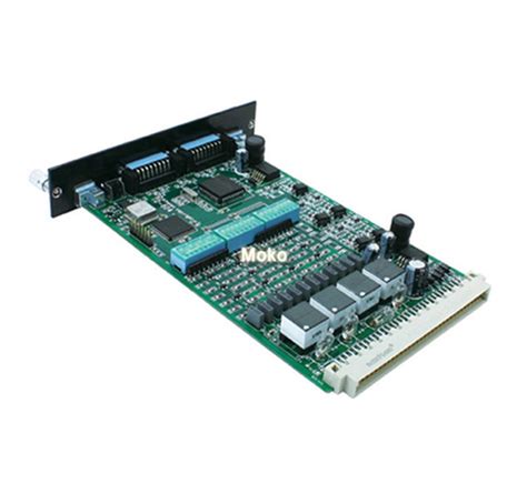
Cost Implications of Flex PCB Manufacturing
Flex PCBs, or flexible printed circuit boards, have become increasingly popular in various industries due to their versatility, lightweight nature, and ability to conform to complex shapes. However, despite their numerous advantages, the cost implications of manufacturing flex PCBs can be significant. Understanding these cost factors is crucial for businesses considering the adoption of this technology.
To begin with, the materials used in flex PCB manufacturing are inherently more expensive than those used in traditional rigid PCBs.
Flex PCBs are typically made from polyimide or polyester films, which offer the necessary flexibility and thermal stability. These materials, while providing superior performance, come at a higher price point compared to the standard FR4 substrate used in rigid PCBs. Consequently, the initial material costs can substantially impact the overall budget for flex PCB production.
Moreover, the manufacturing process for flex PCBs is more complex and labor-intensive.
Unlike rigid PCBs, which can be produced using well-established and automated processes, flex PCBs require specialized equipment and techniques. For instance, the lamination process for flex PCBs involves multiple layers of flexible materials that must be precisely aligned and bonded. This meticulous process demands a higher level of expertise and attention to detail, leading to increased labor costs. Additionally, the need for specialized machinery and tools further drives up the production expenses.
Another significant cost factor is the yield rate in flex PCB manufacturing.
Due to the delicate nature of the materials and the intricate processes involved, the likelihood of defects and errors is higher compared to rigid PCBs. Issues such as misalignment, delamination, and cracking can occur during production, resulting in a lower yield rate. Consequently, manufacturers may need to produce a larger quantity of flex PCBs to achieve the desired number of functional units, thereby increasing the overall cost.
Furthermore, the design and prototyping stages for flex PCBs can be more time-consuming and costly.
The unique properties of flexible materials necessitate careful consideration of factors such as bend radius, mechanical stress, and thermal expansion. Designers must employ advanced simulation tools and conduct thorough testing to ensure the reliability and performance of the final product. This iterative process can extend the development timeline and incur additional expenses, particularly when multiple design revisions are required.
In addition to the direct manufacturing costs, there are also indirect expenses associated with flex PCBs.
For example, the need for specialized packaging and handling solutions to protect the delicate flex circuits during transportation and assembly can add to the overall cost. Moreover, the integration of flex PCBs into existing systems may require modifications to the assembly process and equipment, leading to further investments.
Despite these cost implications, it is important to recognize that the benefits of flex PCBs can often outweigh the expenses.
Their ability to reduce weight, save space, and enhance design flexibility can result in significant advantages for certain applications, such as wearable devices, medical equipment, and aerospace systems. Therefore, businesses must carefully evaluate the trade-offs between cost and performance when considering the adoption of flex PCBs.
In conclusion, while the cost implications of flex PCB manufacturing are considerable, they are justified by the unique advantages that this technology offers. By understanding the various cost factors and carefully planning the design and production processes, businesses can make informed decisions and leverage the benefits of flex PCBs to achieve their specific goals.

