Flex pcb maximum current
Understanding Maximum Current Capacity in Flex PCBs
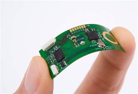
In the realm of modern electronics, flexible printed circuit boards (flex PCBs) have emerged as a pivotal component, offering unparalleled versatility and adaptability. As these circuits are increasingly integrated into a wide array of applications, understanding their maximum current capacity becomes crucial for ensuring both performance and reliability. The maximum current capacity of a flex PCB is determined by several factors, including the material properties, design specifications, and environmental conditions. By comprehensively examining these elements, engineers and designers can optimize the functionality of flex PCBs while mitigating potential risks associated with overheating and circuit failure.
To begin with, the material composition of a flex PCB plays a significant role in determining its current-carrying capacity.
Typically, flex PCBs are constructed using a combination of polyimide substrates and copper conductors. The thickness of the copper layer is a critical factor, as it directly influences the amount of current the circuit can safely carry. Thicker copper layers can handle higher currents, but they also add to the overall weight and cost of the PCB. Therefore, a balance must be struck between current capacity and other design considerations. Additionally, the thermal conductivity of the substrate material affects heat dissipation, which is vital for maintaining the integrity of the circuit under load.
Moreover, the design of the flex PCB itself is instrumental in defining its maximum current capacity.
Trace width and spacing are key design parameters that must be carefully calculated. Wider traces can accommodate higher currents, reducing the risk of overheating. However, increasing trace width may not always be feasible due to space constraints, especially in compact electronic devices. Consequently, designers often employ advanced simulation tools to optimize trace layouts, ensuring that the PCB can handle the required current without compromising on size or functionality. Furthermore, the use of vias and additional layers can enhance current distribution, although these solutions may introduce complexity and cost.
In addition to material and design considerations, environmental factors also impact the maximum current capacity of flex PCBs.
Operating temperature is a critical variable, as higher temperatures can exacerbate the risk of thermal failure. It is essential to account for the ambient temperature and any additional heat generated by nearby components when determining the current capacity. Implementing effective thermal management strategies, such as heat sinks or active cooling systems, can help maintain safe operating conditions. Additionally, humidity and exposure to corrosive substances can degrade the materials used in flex PCBs, potentially affecting their electrical performance over time.
In conclusion, understanding the maximum current capacity of flex PCBs is a multifaceted challenge that requires careful consideration of material properties, design parameters, and environmental conditions. By addressing these factors, engineers can ensure that flex PCBs operate efficiently and reliably within their intended applications. As technology continues to advance, the demand for high-performance, flexible circuits will only grow, underscoring the importance of optimizing their current-carrying capabilities. Through ongoing research and innovation, the electronics industry can continue to push the boundaries of what is possible with flex PCBs, paving the way for new and exciting applications in the future.
Factors Affecting Current Carrying Capacity in Flexible Circuits
Flexible printed circuit boards (PCBs) have become an integral component in modern electronic devices due to their lightweight, compact, and versatile nature. However, understanding the factors that affect their current carrying capacity is crucial for ensuring optimal performance and reliability. The current carrying capacity of a flexible circuit is influenced by several interrelated factors, each playing a significant role in determining how much current the circuit can safely handle.
One of the primary factors affecting the current carrying capacity is the thickness of the copper traces.
Thicker copper layers can carry more current due to their lower resistance, which reduces the amount of heat generated as current flows through the circuit. However, increasing the thickness of the copper also adds to the weight and cost of the flexible PCB, necessitating a careful balance between performance and practicality. In addition to thickness, the width of the copper traces is equally important. Wider traces provide a larger surface area for current to flow, thereby reducing resistance and heat buildup. Designers must consider both the width and thickness of the traces to optimize the current carrying capacity without compromising the flexibility and form factor of the circuit.
Another critical factor is the ambient temperature in which the flexible circuit operates.
Higher temperatures can significantly impact the current carrying capacity by increasing the resistance of the copper traces. This, in turn, leads to greater heat generation, which can exacerbate the risk of thermal damage to the circuit. Therefore, it is essential to account for the operating environment when designing flexible PCBs, ensuring that they can withstand the expected temperature ranges without degradation in performance. Additionally, the thermal management of the circuit, including the use of heat sinks or thermal vias, can help dissipate excess heat and maintain the integrity of the circuit under high current loads.
The material properties of the substrate used in flexible PCBs also play a vital role in determining their current carrying capacity.
The substrate must possess adequate thermal conductivity to effectively dissipate heat generated by the current flow. Materials with higher thermal conductivity can help maintain lower operating temperatures, thereby enhancing the current carrying capacity. Furthermore, the mechanical properties of the substrate, such as its flexibility and tensile strength, must be considered to ensure that the circuit can withstand bending and flexing without compromising its electrical performance.
Moreover, the design layout of the flexible circuit can influence its ability to carry current.
The arrangement of traces, vias, and pads should be optimized to minimize resistance and avoid potential bottlenecks that could lead to localized heating. Careful consideration of the circuit’s layout can help distribute current evenly across the traces, reducing the risk of overheating and ensuring reliable operation.
In conclusion, the current carrying capacity of flexible PCBs is determined by a complex interplay of factors, including copper trace dimensions, ambient temperature, substrate material properties, and circuit design layout. By carefully considering these elements during the design and manufacturing process, engineers can optimize the performance and reliability of flexible circuits, ensuring they meet the demands of modern electronic applications. Understanding these factors is essential for developing flexible PCBs that can safely and efficiently handle the required current loads, thereby contributing to the advancement of electronic technology.

Designing Flex PCBs for Optimal Current Handling
When designing flexible printed circuit boards (PCBs) for optimal current handling, several critical factors must be considered to ensure both performance and reliability. Flex PCBs, known for their adaptability and space-saving advantages, are increasingly used in various applications, from consumer electronics to medical devices. However, their unique structure requires careful attention to current-carrying capabilities to prevent overheating and ensure longevity.
To begin with, understanding the material properties of flex PCBs is essential.
Unlike rigid PCBs, flex circuits are made from flexible substrates such as polyimide, which offer excellent thermal stability and mechanical flexibility. These materials, while advantageous, also impose certain limitations on current capacity. The thickness of the copper traces, the width of the traces, and the overall design layout significantly influence the maximum current a flex PCB can handle. Therefore, selecting the appropriate copper thickness is crucial. Thicker copper layers can carry more current but may reduce the flexibility of the PCB, necessitating a balance between current capacity and mechanical performance.
Moreover, the trace width plays a pivotal role in current handling.
Wider traces can accommodate higher currents, reducing the risk of overheating. However, the available space on a flex PCB is often limited, requiring designers to optimize trace width without compromising the board’s compactness. Advanced design software can assist in calculating the optimal trace width based on the expected current load and the specific application’s thermal requirements.
In addition to trace width and copper thickness, the layout of the flex PCB must be meticulously planned.
The arrangement of traces should minimize resistance and avoid sharp bends, which can create stress points and potential failure sites. Utilizing a serpentine pattern for traces can help distribute mechanical stress more evenly, enhancing the board’s durability under dynamic conditions. Furthermore, incorporating thermal reliefs and vias can aid in heat dissipation, preventing localized hotspots that could degrade the board’s performance over time.
Transitioning to the topic of environmental considerations, it is important to recognize that the operating environment significantly impacts a flex PCB’s current handling capabilities.
High ambient temperatures can exacerbate thermal issues, necessitating additional design measures such as thermal management solutions. Implementing heat sinks or integrating thermal interface materials can effectively dissipate excess heat, ensuring the PCB operates within safe temperature limits.
Furthermore, the choice of connectors and components also influences the current handling capacity of flex PCBs.
Selecting components with appropriate current ratings and ensuring secure connections can prevent bottlenecks and potential failure points. Additionally, considering the potential for electromagnetic interference (EMI) is vital, as it can affect the board’s performance. Employing shielding techniques and maintaining adequate spacing between traces can mitigate EMI issues, ensuring reliable operation.
In conclusion, designing flex PCBs for optimal current handling requires a comprehensive approach that considers material properties, trace design, layout optimization, and environmental factors. By carefully balancing these elements, designers can create flex PCBs that not only meet the current demands of their applications but also maintain reliability and performance over their operational lifespan. As technology continues to advance, the demand for efficient and robust flex PCB designs will only grow, underscoring the importance of mastering these design principles.
Innovations in Flex PCB Materials for Enhanced Current Capacity
In recent years, the demand for flexible printed circuit boards (flex PCBs) has surged, driven by their versatility and adaptability in various applications, from consumer electronics to medical devices. As these applications become more sophisticated, the need for flex PCBs to handle higher current capacities has become increasingly critical. Innovations in flex PCB materials have played a pivotal role in enhancing their current-carrying capabilities, ensuring that they meet the rigorous demands of modern technology.
To begin with, the fundamental structure of a flex PCB involves a thin, flexible substrate, typically made from polyimide or polyester materials.
These substrates are chosen for their excellent thermal stability and mechanical flexibility. However, the challenge lies in their ability to conduct higher currents without compromising the integrity of the circuit. Traditional copper traces, while effective, have limitations in terms of current capacity due to their thickness and width constraints. Consequently, researchers and manufacturers have been exploring alternative materials and techniques to overcome these limitations.
One significant innovation in this area is the development of advanced copper alloys and composite materials.
These materials offer improved electrical conductivity and thermal performance, allowing for thinner traces that can carry higher currents. By incorporating elements such as silver or nickel into the copper matrix, these alloys enhance the overall conductivity and reduce resistive losses. This advancement not only increases the current capacity but also contributes to the miniaturization of electronic devices, as thinner traces occupy less space on the flex PCB.
Moreover, the use of conductive adhesives and inks has emerged as a promising solution for enhancing current capacity.
These materials can be printed directly onto the flexible substrate, forming conductive paths that are both efficient and reliable. Conductive inks, often composed of silver nanoparticles, provide excellent conductivity while maintaining flexibility. This approach allows for the creation of complex circuit patterns without the need for traditional etching processes, thereby reducing manufacturing costs and time.
In addition to material innovations, advancements in fabrication techniques have also contributed to the enhanced current capacity of flex PCBs.
Laser direct structuring (LDS) is one such technique that has gained traction. LDS enables the precise deposition of conductive materials onto the substrate, allowing for the creation of intricate circuit designs with high current-carrying capabilities. This method not only improves the electrical performance of the flex PCB but also enhances its mechanical durability, making it suitable for applications that require repeated bending and flexing.
Furthermore, thermal management has become a crucial consideration in the design of flex PCBs with high current capacity.
Efficient heat dissipation is essential to prevent overheating and ensure the longevity of the circuit. To address this, manufacturers are incorporating advanced thermal interface materials and heat spreaders into the design of flex PCBs. These components help to distribute heat evenly across the board, reducing hotspots and maintaining optimal operating temperatures.
In conclusion, the innovations in flex PCB materials and fabrication techniques have significantly enhanced their current-carrying capabilities, meeting the demands of increasingly complex electronic applications. By leveraging advanced copper alloys, conductive inks, and cutting-edge manufacturing processes, flex PCBs are now able to handle higher currents while maintaining their inherent flexibility and reliability. As technology continues to evolve, these advancements will undoubtedly play a crucial role in shaping the future of flexible electronics, enabling new possibilities and applications across various industries.