From SCH to PCB: A Detailed Step-by-Step Guide
Introduction
The process of transforming a schematic (SCH) into a printed circuit board (PCB) is a fundamental workflow in electronics design. This conversion bridges the conceptual electrical design with the physical implementation, requiring careful attention to detail at every stage. For engineers and designers, mastering this transition is crucial for creating functional, reliable, and manufacturable electronic products.
This comprehensive guide will walk through the entire process from schematic capture to finished PCB layout, covering all critical steps, best practices, and potential pitfalls to avoid. Whether you’re using Altium Designer, KiCad, Eagle, or another ECAD tool, these fundamental principles apply across most PCB design platforms.
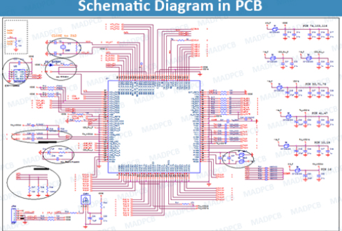
Step 1: Complete and Verify the Schematic Design
Before even considering the PCB layout, you must have a complete and error-free schematic:
- Finalize component selection: Ensure all components have appropriate footprints and are available for procurement
- Verify electrical connections: Double-check that all nets are properly connected
- Add design notes: Include any special requirements (high voltage, RF, etc.)
- Run ERC (Electrical Rule Check): Most ECAD tools include this to catch common errors
- Confirm power requirements: Verify voltage levels and current requirements are properly annotated
Common mistake: Neglecting to properly annotate component values or forgetting to assign footprints at this stage will cause problems later.
Step 2: Prepare for PCB Layout
With the schematic verified, prepare for the transition to PCB:
- Create a new PCB document in your ECAD tool
- Set up the board outline based on mechanical constraints
- Configure design rules:
- Trace width (consider current requirements)
- Clearance rules (signal-to-signal, power, etc.)
- Via sizes and types
- Layer stackup configuration
- Import netlist from the schematic (typically automated in modern tools)
- Verify component footprints: Visually check that all components have correct footprints
Pro tip: Establish your design rules before placing components to avoid having to rework the layout later.
Step 3: Component Placement
Strategic component placement significantly impacts the board’s performance and manufacturability:
- Place connectors and mechanical components first (fixed position items)
- Position critical components (ICs, processors, RF components) considering:
- Signal flow
- Thermal management
- Decoupling capacitor proximity
- Arrange supporting components (resistors, capacitors, etc.) near their associated ICs
- Group functional blocks together (power supply, analog, digital sections)
- Consider manufacturing requirements:
- Minimum spacing for pick-and-place machines
- Orientation for automated assembly
- Accessibility for rework if needed
Best practice: Use the schematic as a guide for placement—components that are connected should generally be placed near each other.
Step 4: Routing the PCB
With components placed, begin creating the physical connections:
- Route critical signals first:
- High-speed signals (controlled impedance, length matching)
- Sensitive analog signals
- Clock lines
- Power and ground
- Establish power distribution network:
- Use planes where possible
- Consider current requirements for trace widths
- Implement proper decoupling
- Route general signals:
- Avoid 90° angles (use 45°)
- Minimize via usage where possible
- Implement ground strategy:
- Decide between ground planes or ground grids
- Ensure proper return paths
- Run DRC (Design Rule Check) frequently to catch issues early
Advanced technique: Use different trace widths for different current requirements—a handy formula is Trace Width (mils) = (Current (A)/(k*(Temp Rise (°C))^b))^(1/c), where k, b, and c are constants based on copper layer location.
Step 5: Copper Pour and Plane Creation
Improve signal integrity and reduce noise:
- Add ground planes on inner layers (for multilayer boards)
- Create copper pours for:
- Shielding
- Thermal management
- Reduced EMI
- Set appropriate clearance between pours and other elements
- Connect pours properly (especially ground) with multiple vias
Important: Be mindful of creating unintended antennas with copper pours—ensure proper stitching and connections.
Step 6: Silkscreen and Documentation
Add reference information to the board:
- Position reference designators clearly near components
- Add polarity markers and pin 1 indicators
- Include version information and copyright notices
- Add test points and measurement references
- Place assembly markings if needed
- Ensure text is legible and won’t be covered by components
Helpful hint: Use contrasting silkscreen colors (white on green solder mask is standard) and sufficient font sizes.
Step 7: Final Verification
Before generating manufacturing files:
- Run final DRC with all rules enabled
- Verify netlist consistency between schematic and PCB
- Check for unconnected pins
- Review layer-by-layer for errors
- Confirm manufacturing requirements:
- Minimum trace/space
- Drill sizes
- Solder mask clearance
- Perform visual inspection (3D view if available)
Critical step: Have a second engineer review the design if possible—fresh eyes often catch overlooked issues.
Step 8: Generate Manufacturing Files
Output the files needed for fabrication and assembly:
- Gerber files (one per layer plus drill files)
- RS-274X format is standard
- Include all necessary layers (copper, silkscreen, solder mask, etc.)
- Drill files (Excellon format typically)
- Separate files for plated and non-plated holes if needed
- Pick-and-place file for assembly
- Bill of Materials (BOM) with complete procurement information
- Assembly drawings if required
- Readme file with special instructions
Modern alternative: Some manufacturers now accept native design files (like .brd or .PcbDoc) with ODB++ becoming a popular comprehensive format.
Step 9: Design Review and Feedback
Before sending to fabrication:
- Review with manufacturing partner if possible
- Consider running a DFM check (many online tools available)
- Verify all special requirements are met
- Confirm file compatibility with manufacturer’s equipment
Cost-saving tip: Many manufacturers offer free design reviews that can catch potential issues before fabrication.
Step 10: Prototype and Iterate
After receiving the first boards:
- Inspect physical PCB against design
- Test functionality thoroughly
- Document any issues for the next revision
- Consider design improvements:
- Component placement adjustments
- Routing optimizations
- Enhanced manufacturability
Reality check: Most designs require at least one revision—factor this into your development timeline.
Advanced Considerations
For more complex designs:
- Signal integrity analysis for high-speed designs
- Thermal analysis for power-dense boards
- EMC/EMI simulations for compliance-critical products
- Flex/Rigid-flex specific requirements if applicable
- HDI techniques for dense designs (microvias, buried vias)
Common Pitfalls to Avoid
- Incorrect footprints (verify against actual components)
- Insufficient power distribution (calculate current needs)
- Improper grounding leading to noise issues
- Violating manufacturer capabilities (know their limits)
- Overlooking thermal considerations (check power dissipation)
- Neglecting testability (include test points)
Conclusion
The transition from schematic to PCB is both an art and a science, requiring attention to electrical requirements, physical constraints, and manufacturing realities. By following this systematic approach—from schematic completion through final verification—you can create PCBs that are electrically sound, reliable, and manufacturable.
Remember that PCB design is an iterative process. Even experienced engineers typically go through multiple revisions to optimize their designs. Each project presents unique challenges, but mastering these fundamental steps will provide a solid foundation for all your PCB design work.
As you gain experience, you’ll develop intuition for component placement, routing strategies, and design trade-offs. The most successful PCB designers combine technical knowledge with practical experience—so don’t be discouraged by initial challenges. With each board you design, you’ll refine your skills and develop more efficient workflows.
Finally, always keep learning. PCB technology and design tools continue to evolve, offering new techniques and capabilities that can improve your designs. Stay current with industry trends, new materials, and advanced design methodologies to take your PCB designs from good to great.