High-Reliability PCBs: Design, Materials, and Manufacturing Considerations
Introduction
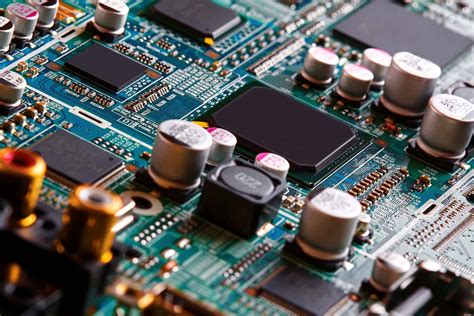
Printed Circuit Boards (PCBs) are the backbone of modern electronics, enabling the interconnection of components in devices ranging from consumer electronics to aerospace systems. While standard PCBs suffice for everyday applications, high-reliability PCBs are essential for industries where failure is not an option—such as medical devices, military and aerospace systems, automotive electronics, and industrial automation.
High-reliability PCBs are designed to withstand extreme conditions, including high temperatures, mechanical stress, humidity, and prolonged operational life. Achieving such reliability requires careful consideration of design principles, material selection, manufacturing processes, and testing protocols. This article explores the key aspects of high-reliability PCBs, including their design considerations, material choices, manufacturing techniques, and testing methodologies.
1. Key Characteristics of High-Reliability PCBs
High-reliability PCBs differ from standard PCBs in several critical aspects:
- Extended Lifespan: Designed to operate reliably for years or even decades without failure.
- Robust Performance in Harsh Environments: Resistant to thermal cycling, vibration, moisture, and chemical exposure.
- Strict Compliance with Industry Standards: Must meet IPC (Association Connecting Electronics Industries) Class 3, MIL-PRF-31032, or other industry-specific certifications.
- Superior Material Quality: Uses high-performance substrates, copper, and solder masks to ensure durability.
- Advanced Testing and Inspection: Undergoes rigorous electrical, thermal, and mechanical testing to detect defects early.
2. Design Considerations for High-Reliability PCBs
2.1. Thermal Management
Excessive heat is a leading cause of PCB failure. High-reliability PCBs must efficiently dissipate heat to prevent component degradation. Design strategies include:
- Thermal Vias: Plated holes that transfer heat from components to heat sinks or inner layers.
- Copper Thickness and Distribution: Thicker copper layers improve heat dissipation.
- High-Tg (Glass Transition Temperature) Materials: Substrates with high Tg (e.g., >170°C) resist thermal deformation.
2.2. Signal Integrity and EMI Shielding
High-speed and high-frequency applications require controlled impedance and minimal electromagnetic interference (EMI). Techniques include:
- Proper Trace Routing: Avoiding sharp angles and maintaining consistent trace widths.
- Ground Planes and Shielding: Using multilayer designs with dedicated ground planes to reduce noise.
- Differential Pair Routing: Ensuring balanced signal paths to minimize crosstalk.
2.3. Mechanical Durability
PCBs in aerospace, automotive, and industrial applications must endure mechanical stress. Design enhancements include:
- Reinforced Board Edges: Preventing delamination under vibration.
- Flex-Rigid PCBs: Combining rigid and flexible sections for shock absorption.
- Conformal Coating: Protective coatings (e.g., acrylic, silicone, or parylene) to resist moisture and corrosion.
2.4. Redundancy and Fault Tolerance
Critical systems often incorporate redundancy, such as:
- Duplicate Traces and Components: Ensuring continued operation if one path fails.
- Built-in Self-Test (BIST) Circuits: Automatically detecting faults during operation.
3. Material Selection for High-Reliability PCBs
3.1. Substrate Materials
The base material (laminate) significantly impacts reliability. Common high-reliability substrates include:
- FR-4 High Tg: Standard FR-4 with enhanced thermal resistance (Tg ≥ 170°C).
- Polyimide: Excellent thermal stability and flexibility, used in aerospace and military applications.
- Ceramic-Based PCBs: Superior thermal conductivity for high-power applications.
- PTFE (Teflon): Low dielectric loss for high-frequency RF/microwave circuits.
3.2. Copper Foil Quality
High-reliability PCBs use:
- Electrodeposited (ED) Copper: Standard for most applications.
- Rolled Annealed Copper: Smoother surface, better for high-frequency signals.
- Heavy Copper PCBs (≥3 oz): For high-current applications.
3.3. Solder Mask and Surface Finishes
- Solder Mask: Liquid Photoimageable (LPI) solder masks provide better adhesion and chemical resistance.
- Surface Finishes:
- ENIG (Electroless Nickel Immersion Gold): Excellent solderability and corrosion resistance.
- OSP (Organic Solderability Preservative): Cost-effective but less durable.
- Immersion Silver/Tin: Good for high-frequency applications.
4. Manufacturing Processes for High-Reliability PCBs
4.1. Controlled Impedance PCB Fabrication
High-speed designs require precise impedance control, achieved through:
- Laser-Drilled Microvias: For high-density interconnects (HDI).
- Strict Dielectric Thickness Control: Ensuring consistent signal propagation.
4.2. Advanced Lamination Techniques
- Sequential Lamination: For multilayer boards with buried vias.
- Low-Pressure Lamination: Reducing resin flow for better layer alignment.
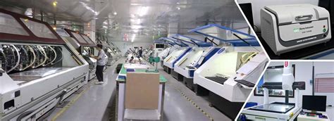
4.3. Automated Optical Inspection (AOI) and X-Ray Inspection
- AOI: Detects soldering defects, misalignments, and trace imperfections.
- X-Ray Inspection: Verifies internal layer integrity and via quality.
4.4. Conformal Coating and Encapsulation
- Silicone Coatings: Flexible and heat-resistant.
- Parylene Coating: Ultra-thin, chemically inert, and biocompatible (used in medical devices).
5. Testing and Qualification of High-Reliability PCB
5.1. Electrical Testing
- Continuity and Isolation Tests: Ensuring no short or open circuits.
- High-Voltage Testing: Verifying insulation resistance.
5.2. Environmental Stress Testing
- Thermal Cycling (-55°C to +125°C): Simulates extreme temperature fluctuations.
- Humidity Testing (85°C/85% RH): Assesses moisture resistance.
- Vibration and Shock Testing: Validates mechanical robustness.
5.3. Accelerated Life Testing (ALT)
- HALT (Highly Accelerated Life Test): Rapidly identifies failure modes.
- MTBF (Mean Time Between Failures) Analysis: Predicts long-term reliability.
6. Applications of High-Reliability PCBs
- Aerospace & Defense: Avionics, satellites, missile guidance systems.
- Medical Devices: Implantable electronics, diagnostic equipment.
- Automotive: Engine control units (ECUs), ADAS systems.
- Industrial: Oil & gas sensors, power grid controls.
Conclusion
High-reliability PCBs are critical for mission-critical applications where failure can have severe consequences. Achieving reliability demands meticulous design, superior materials, precision manufacturing, and rigorous testing. As technology advances, the demand for even more robust PCBs will grow, pushing innovation in materials science, fabrication techniques, and quality assurance methodologies.
By adhering to industry standards and leveraging cutting-edge technologies, manufacturers can produce PCBs that meet the stringent demands of high-reliability applications, ensuring long-term performance and safety.
This article provides a comprehensive overview of high-reliability PCBs, covering design, materials, manufacturing, and testing. Let me know if you’d like any section expanded or modified!