How are rigid flex pcbs made
Materials And Components Used In Rigid Flex PCB Manufacturing
Rigid-flex PCBs, or rigid-flex printed circuit boards, are a hybrid of rigid and flexible circuit boards, offering a unique combination of the benefits of both types. The manufacturing process of rigid-flex PCBs involves a variety of materials and components, each playing a crucial role in ensuring the final product meets the desired specifications and performance standards. Understanding the materials and components used in rigid-flex PCB manufacturing is essential for appreciating the complexity and precision involved in their production.
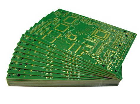
To begin with, the base materials for rigid-flex PCBs include a combination of rigid and flexible substrates.
The rigid sections are typically made from materials such as FR4, a glass-reinforced epoxy laminate known for its excellent mechanical and electrical properties. FR4 provides the necessary rigidity and structural support for components that require a stable platform. On the other hand, the flexible sections are usually made from polyimide, a high-performance polymer known for its flexibility, thermal stability, and resistance to chemicals. Polyimide allows the flexible sections to bend and twist without compromising the integrity of the circuit.
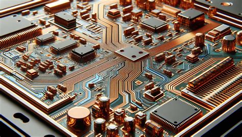
In addition to the base materials, copper is a critical component in rigid-flex PCB manufacturing.
Copper foils are laminated onto the rigid and flexible substrates to form the conductive pathways that enable electrical connections between components. The thickness of the copper layer can vary depending on the specific requirements of the PCB, with common thicknesses ranging from 1 oz/ft² to 3 oz/ft². The copper layers are then etched to create the desired circuit patterns, a process that requires precision and accuracy to ensure the correct functionality of the PCB.
Another essential material in rigid-flex PCB manufacturing is the adhesive used to bond the rigid and flexible sections together.
The adhesive must provide a strong bond while maintaining flexibility and thermal stability. Common adhesives include epoxy and acrylic-based formulations, which offer excellent adhesion properties and can withstand the thermal cycling and mechanical stresses encountered during the PCB’s operation.
Furthermore, the manufacturing process involves the use of coverlays and solder masks.
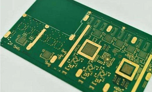
Coverlays are protective layers applied to the flexible sections of the PCB to shield the copper traces from environmental factors such as moisture, dust, and mechanical abrasion. They are typically made from polyimide films coated with adhesive and are laminated onto the flexible substrate. Solder masks, on the other hand, are applied to the rigid sections to protect the copper traces from oxidation and to prevent solder bridges during the assembly process. Solder masks are usually made from epoxy-based resins and are available in various colors, with green being the most common.
Additionally, stiffeners are often used in rigid-flex PCB manufacturing to provide additional support and rigidity to specific areas of the flexible sections.
Stiffeners can be made from materials such as FR4, polyimide, or stainless steel, depending on the required level of support and the specific application of the PCB. They are typically bonded to the flexible substrate using adhesive and help to prevent excessive bending and mechanical stress in critical areas.
In conclusion, the materials and components used in rigid-flex PCB manufacturing are carefully selected to ensure the final product meets the desired performance and reliability standards. The combination of rigid and flexible substrates, copper foils, adhesives, coverlays, solder masks, and stiffeners all play a crucial role in the manufacturing process. Each material and component must be precisely engineered and integrated to create a high-quality rigid-flex PCB capable of withstanding the demands of various applications.
Step-By-Step Process Of Rigid Flex PCB Fabrication
The fabrication of rigid-flex printed circuit boards (PCBs) is a meticulous process that combines the benefits of both rigid and flexible circuits, resulting in a versatile and durable product. This process begins with the design phase, where engineers use specialized software to create a detailed blueprint of the PCB. The design must account for the unique requirements of rigid-flex PCBs, such as the need for precise alignment between the rigid and flexible sections and the integration of multiple layers.
Once the design is finalized, the next step involves selecting the appropriate materials.
Rigid-flex PCBs typically use a combination of rigid materials like FR4 and flexible materials such as polyimide. These materials are chosen for their ability to withstand various environmental conditions and mechanical stresses. The rigid sections provide structural support, while the flexible sections allow for bending and folding, making the PCB suitable for complex applications.
Following material selection, the fabrication process moves to the creation of the individual layers.
This involves etching the copper layers to form the circuit patterns. The etching process is carried out using a photolithographic technique, where a photoresist is applied to the copper surface and exposed to ultraviolet light through a mask that defines the circuit pattern. The exposed areas are then developed, and the unprotected copper is etched away, leaving behind the desired circuit traces.
After etching, the layers are laminated together.
This step is crucial as it ensures the integrity and alignment of the multiple layers. The flexible layers are sandwiched between the rigid layers, and the entire stack is subjected to heat and pressure to bond the materials together. This lamination process must be carefully controlled to prevent any misalignment or defects that could compromise the functionality of the PCB.
Once the layers are laminated, the next step is drilling.
Precision drilling is required to create vias, which are small holes that allow electrical connections between different layers of the PCB. These vias are then plated with copper to ensure reliable conductivity. The drilling process must be highly accurate to avoid damaging the delicate flexible sections and to maintain the integrity of the electrical connections.
Following drilling and plating, the PCB undergoes a series of inspections and tests to ensure quality and functionality.
Automated optical inspection (AOI) systems are used to check for any defects in the circuit patterns, while electrical tests verify the continuity and integrity of the connections. Any issues identified during these inspections must be addressed before proceeding to the next stage.
The final steps in the fabrication process involve applying a solder mask and surface finish.
The solder mask is a protective layer that prevents solder bridges and protects the copper traces from oxidation. The surface finish, such as HASL (Hot Air Solder Leveling) or ENIG (Electroless Nickel Immersion Gold), is applied to the exposed copper pads to enhance solderability and protect against corrosion.
In conclusion, the fabrication of rigid-flex PCBs is a complex and precise process that requires careful planning, material selection, and execution. Each step, from design and material selection to etching, lamination, drilling, and finishing, must be meticulously carried out to ensure the final product meets the required specifications and performance standards. This intricate process results in a versatile and durable PCB that can be used in a wide range of applications, from consumer electronics to aerospace and medical devices.
Quality Control And Testing In Rigid Flex PCB Production
Quality control and testing are critical components in the production of rigid-flex PCBs, ensuring that the final product meets stringent industry standards and performs reliably in its intended application. The process begins with the inspection of raw materials, where suppliers provide certification of compliance with specified requirements. This initial step is crucial as it sets the foundation for the entire manufacturing process. Any deviation in material quality can lead to significant issues down the line, affecting the performance and durability of the PCB.
Following the material inspection, the manufacturing process itself is closely monitored.
During the fabrication of rigid-flex PCBs, various stages such as drilling, plating, and etching are meticulously controlled. Automated optical inspection (AOI) systems are employed to detect any defects in the circuitry. These systems use high-resolution cameras and advanced algorithms to identify issues such as misalignments, shorts, and opens. By catching these defects early, manufacturers can address them before they become more problematic and costly to fix.
In addition to AOI, electrical testing is performed to verify the integrity of the circuits.
This involves checking for continuity and isolation to ensure that the electrical pathways are correctly formed and that there are no unintended connections. Flying probe testers and bed-of-nails testers are commonly used for this purpose. These tests are essential for confirming that the PCB will function as designed when integrated into the final product.
Thermal cycling and environmental stress testing are also integral parts of the quality control process.
Rigid-flex PCBs are often used in applications that require high reliability under varying environmental conditions. Therefore, they must be tested for their ability to withstand temperature fluctuations, humidity, and mechanical stress. Thermal cycling tests involve repeatedly heating and cooling the PCB to simulate real-world operating conditions. Environmental stress testing, on the other hand, subjects the PCB to conditions such as high humidity and vibration to ensure that it can endure the rigors of its intended use.
Another critical aspect of quality control is the inspection of the flex-to-rigid transitions.
These areas are particularly susceptible to mechanical stress and must be carefully examined to ensure that they are free from defects. X-ray inspection is often used to check for issues such as voids and delamination in these critical areas. By using X-ray technology, manufacturers can see inside the PCB and identify potential problems that are not visible to the naked eye.
Furthermore, solderability testing is conducted to ensure that the PCB can be reliably assembled with other components.
This involves testing the surface finish of the PCB to confirm that it can form strong, reliable solder joints. Poor solderability can lead to issues such as cold joints and solder bridges, which can compromise the performance and reliability of the final product.
Finally, once all testing and inspections are complete, a comprehensive review of the data is conducted.
This review helps to identify any trends or recurring issues that may need to be addressed in the manufacturing process. Continuous improvement is a key principle in rigid-flex PCB production, and feedback from the quality control process is used to refine and enhance manufacturing techniques.
In conclusion, quality control and testing are indispensable in the production of rigid-flex PCBs. From the inspection of raw materials to the final review of test data, each step is designed to ensure that the PCBs meet the highest standards of quality and reliability. By employing a combination of advanced inspection technologies and rigorous testing protocols, manufacturers can deliver products that perform reliably in even the most demanding applications.

Innovations And Trends In Rigid Flex PCB Manufacturing Techniques
Rigid-flex printed circuit boards (PCBs) have become increasingly popular in various industries due to their unique combination of flexibility and rigidity, which allows for more complex and compact electronic designs. The manufacturing techniques for rigid-flex PCBs have evolved significantly, driven by innovations and trends that aim to enhance performance, reliability, and cost-effectiveness. Understanding these advancements provides insight into the sophisticated processes involved in creating these versatile components.
One of the primary innovations in rigid-flex PCB manufacturing is the use of advanced materials.
Traditional PCBs typically use FR4, a glass-reinforced epoxy laminate, for the rigid sections. However, rigid-flex PCBs incorporate flexible polyimide films for the flexible sections, which offer excellent thermal stability and mechanical properties. The integration of these materials requires precise control and expertise to ensure seamless transitions between rigid and flexible areas. This material innovation has enabled the production of PCBs that can withstand harsh environments and mechanical stress, making them ideal for applications in aerospace, medical devices, and consumer electronics.
Another significant trend is the miniaturization of components.
As electronic devices become smaller and more powerful, the demand for compact and efficient PCBs has increased. Rigid-flex PCBs are particularly well-suited for this trend due to their ability to fold and bend, allowing for more efficient use of space within a device. Manufacturers have developed advanced techniques such as laser drilling and high-density interconnect (HDI) technology to create finer traces and smaller vias, which are essential for miniaturized designs. These techniques enable the production of PCBs with higher component density and improved electrical performance.
The adoption of automated manufacturing processes has also revolutionized rigid-flex PCB production.
Automation enhances precision and repeatability, reducing the likelihood of human error and improving overall quality. For instance, automated optical inspection (AOI) systems are now commonly used to detect defects in PCBs during various stages of production. Additionally, automated assembly lines equipped with robotic arms and pick-and-place machines ensure accurate placement of components, further enhancing the reliability of the final product. This shift towards automation has not only increased production efficiency but also reduced costs, making rigid-flex PCBs more accessible to a broader range of industries.
Moreover, advancements in design software have played a crucial role in the evolution of rigid-flex PCB manufacturing.
Modern design tools offer sophisticated simulation and modeling capabilities, allowing engineers to optimize their designs before production. These tools can simulate the mechanical and thermal behavior of the PCB, identify potential issues, and suggest improvements. This iterative design process helps in creating more robust and reliable PCBs, reducing the need for costly revisions and rework. Furthermore, the integration of design and manufacturing processes through digital twins and Industry 4.0 principles has streamlined the entire production cycle, from concept to final product.
Environmental considerations have also influenced the development of new manufacturing techniques.
The push for greener electronics has led to the adoption of lead-free soldering processes and the use of environmentally friendly materials. Additionally, manufacturers are implementing recycling programs and waste reduction strategies to minimize the environmental impact of PCB production. These efforts align with global sustainability goals and reflect the industry’s commitment to responsible manufacturing practices.
In conclusion, the manufacturing of rigid-flex PCBs has seen remarkable advancements driven by innovations in materials, miniaturization, automation, design software, and environmental sustainability. These trends have collectively enhanced the performance, reliability, and cost-effectiveness of rigid-flex PCBs, making them indispensable in modern electronic devices. As technology continues to evolve, it is likely that further innovations will emerge, pushing the boundaries of what is possible with rigid-flex PCB manufacturing.