
How are Rigid Flex PCBs Made
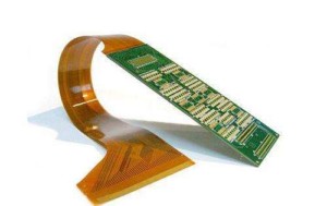
A rigid-flex PCB is a printed circuit board that combines both rigid and flexible board technologies in a single design.
This type of PCB is made up of multiple layers of rigid circuit boards that are interconnected by flexible circuitry.
The rigid sections of the board provide stability and support for components,
while the flexible sections allow the board to bend and twist to fit into tight spaces or conform to unique shapes.
Rigid-flex PCBs are commonly used in applications where space is limited, such as in medical devices, aerospace, and military equipment.
Rigid-flex PCBs are made by combining rigid and flexible PCBs into a single unit. The process involves the following steps:
Rigid-Flex PCB Design Guidelines:
1. Component Placement: Place components on the rigid part of the board, and keep the flexible part clear of components.
2. Trace Routing: Route traces on the rigid part of the board, and avoid routing traces on the flexible part unless absolutely necessary.
3. Bend Radius: Ensure that the bend radius of the flexible part of the board is at least 10 times the thickness of the flexible material.
4. Keepout Zones: Define keepout zones around the flexible part of the board to prevent components from being placed too close to the bend area.
5. Via Placement: Place vias on the rigid part of the board, and avoid placing vias on the flexible part unless absolutely necessary.
6. Copper Weight: Use a thinner copper weight on the flexible part of the board to minimize stress on the material during bending.
7. Coverlay: Use coverlay to protect the flexible part of the board from damage during assembly and use.
8. Test Points: Place test points on the rigid part of the board, and avoid placing them on the flexible part unless absolutely necessary.
9. Solder Mask: Use a thinner solder mask on the flexible part of the board to minimize stress on the material during bending.
10. Documentation: Provide clear documentation and instructions for assembly and testing of the rigid-flex PCB to ensure proper handling and use.
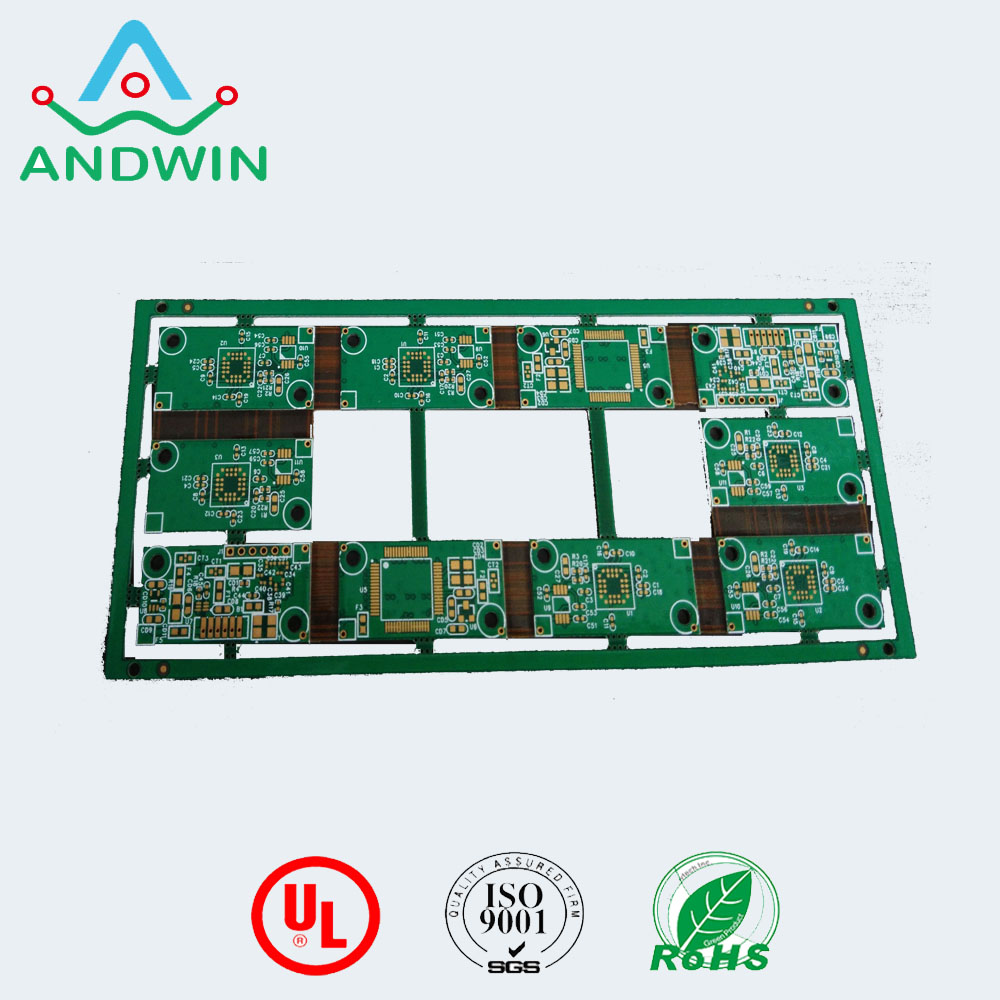
The rigid-flex PCB manufacturing process:
1.Base Preparation
This involves preparation of the laminate. The laminate, in turn, features a copper layer. If the copper contains anti-tarnish, it needs to be removed by immersing it in acid solution.
2.Circuit Patterns / Structure
Through a process of either photo imaging or screen printing, circuit patterns are generated.
3.Circuit Pattern Etching
Etching the circuit pattern is largely done by spraying a solution over the circuit pattern or dipping the laminate in an etching solution. Etching is then undertaken on both sides of the circuit pattern.
4.Drilling Holes
Holes are next drilled using lasers. Laser drilling, in turn, assures precision as well as minimizes waste.
5.Through-hole Plating
Copper is deposited into the drilled holes and plated with a chemical. This step is crucial to create electrical interconnections.
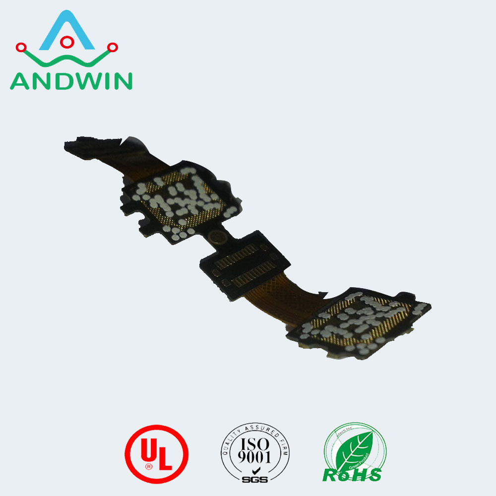
6.Coating Etch-Resist and stripping
This step involves applying a photosensitive etch-resist coating on the substrate. The chemical resist applied to the plated through-hole is next stripped.
7.Cover lay Application
A cover lay is applied to the PCB to protect it from harsh environmental conditions. The coverlay material is screen printed onto the surface of the circuit board and exposed to UV.
8.Cutting the Flex
The individual flex board is now cut from the production panel with extreme caution and precision.
9.Lamination
In this step, the flexible printed circuit boards is laminated between the rigid sections.
10.Electrical Testing and Verification
Electrical testing and verification are the final step that ensures circuit performance and quality.
With the above steps you can rest assured that you will get a performance-driven rigid-flex PCB. The important bit is to choose a contract manufacturer that specializes in the fabrication of rigid-flex PCBs, who can understand your bespoke requirements and deliver accordingly.
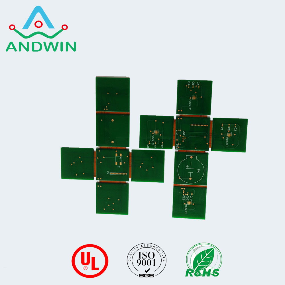
Advantages of Rigid-Flex PCBs
Some of the specific advantages that rigid-flex PCBs offer include:
Stability – With their structure comprising of interchanging layers of rigid and flexible PCBs they offer mechanical stability. They also lend themselves to easy installation in small spaces.
Reliability of connections – Rigid-flex PCBs offer increased stability as well as polarity. This leads to reliable connections.
Cost effectiveness – Rigid-flex PCBs are extremely cost-effective and ensure that your project is viable.
High-density applications – With miniaturization and high-density applications growing in popularity so is the use of rigid-flex PCBs.
High shock and vibration resistance – Rigid flex PCBs are resistant to shock and vibration and find a place in a wide variety of applications.