How does a thermal pad work
A thermal pad works by filling the microscopic gaps and imperfections between two surfaces,
such as a heat-generating component and a heat sink or cooling solution.
These gaps can create air pockets that act as insulators, reducing the efficiency of heat transfer and causing the component to overheat.
The thermal pad is made of a soft, flexible material that conforms to the shape of the surfaces it is placed between.
It is designed to be thermally conductive, meaning it can transfer heat from one surface to another.
When the thermal pad is compressed between the two surfaces, it fills in the gaps and creates a continuous path for heat to flow.

The thermal pad is also designed to be non-conductive, meaning it does not conduct electricity.
This is important because it prevents any electrical current from flowing between the two surfaces,
which could cause damage to the component or the cooling solution.
Overall, the thermal pad helps to improve the efficiency of heat transfer between a heat-generating component and a cooling solution,
reducing the risk of overheating and improving the performance and lifespan of the component.

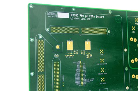
thermal pad pcb design
Thermal pads are used in PCB design to provide a thermal interface between a component and the PCB.
Here are some tips for designing thermal pads in PCBs:
1. Determine the thermal requirements:
Before designing the thermal pad, it is important to determine the thermal requirements of the component.
This includes the maximum operating temperature, the heat dissipation requirements, and the thermal resistance of the component.
2. Choose the right material:
The material used for the thermal pad should have good thermal conductivity and be able to withstand high temperatures.
Copper and aluminum are commonly used materials for thermal pads.
3. Determine the size and shape:
The size and shape of the thermal pad should be designed to match the component.
The pad should be large enough to cover the entire component and provide a good thermal interface.
4. Place the thermal pad correctly:
The thermal pad should be placed in the correct location on the PCB to ensure good thermal contact with the component.
It should also be connected to a ground plane to provide a low thermal resistance path to dissipate heat.
5. Use vias to improve thermal performance:
Vias can be used to improve the thermal performance of the PCB by providing a low thermal resistance path between the thermal pad and the ground plane.
6. Test the thermal performance:
It is important to test the thermal performance of the PCB to ensure that it meets the thermal requirements of the component.
This can be done using thermal imaging or other thermal testing methods.