How to Choose PCB Laminate Materials: A Comprehensive Guide
Introduction
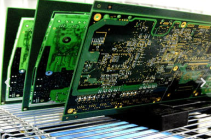
Printed Circuit Board (PCB) laminate materials form the foundation of every electronic circuit, serving as the substrate upon which all components are mounted and interconnected. The selection of appropriate PCB laminate is one of the most critical decisions in board design, directly impacting performance, reliability, manufacturability, and cost. This 2000-word guide provides a comprehensive framework for choosing the right PCB laminate material for your specific application.
Understanding PCB Laminate Basics
Composition of PCB Laminates
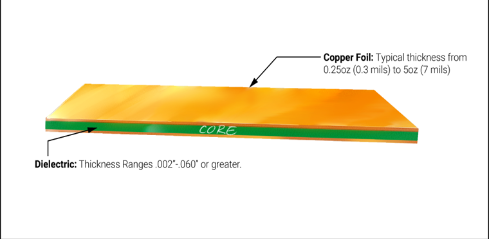
PCB laminates consist of three primary components:
- Reinforcement Material: Typically woven fiberglass (E-glass being most common), but can also include other materials like ceramic or aramid fibers for specialized applications.
- Resin System: The matrix that binds the reinforcement, with epoxy being most prevalent. Other resin systems include polyimide, BT epoxy, cyanate ester, and PTFE.
- Copper Foil: Electrodeposited or rolled copper that forms the conductive layers, available in various weights (typically 0.5 oz to 2 oz per square foot).
Key Laminate Properties
When evaluating PCB laminates, consider these fundamental properties:
- Dielectric Constant (Dk): Affects signal propagation speed and impedance
- Dissipation Factor (Df): Indicates signal loss characteristics
- Thermal Performance: Including Tg (glass transition temperature), Td (decomposition temperature), and CTE (coefficient of thermal expansion)
- Mechanical Strength: Important for rigid boards and applications with mechanical stress
- Moisture Absorption: Affects reliability in humid environments
- Flame Retardancy: Typically UL94-V0 rated for safety
Step-by-Step Laminate Selection Process
1. Define Application Requirements
The first step in laminate selection is understanding your application’s specific needs:
Frequency of Operation:
- Standard digital (<1 GHz): FR-4 typically sufficient
- RF/Microwave (1-10 GHz): Low-loss materials like Rogers RO4000 series
- Millimeter wave (>10 GHz): Ultra-low loss materials with tight Dk tolerance
Operating Environment:
- Commercial: Standard FR-4 adequate
- Automotive: Higher Tg materials for thermal cycling
- Aerospace: Polyimide for extreme temperature ranges
- Marine: Materials with low moisture absorption
Reliability Requirements:
- Consumer electronics: 3-5 year lifespan typical
- Industrial/medical: 10+ years with higher reliability materials
2. Evaluate Electrical Requirements
Signal Integrity Needs:
For high-speed digital or analog signals:
- Tight control of dielectric constant (Dk) for impedance matching
- Low dissipation factor (Df) to minimize signal loss
- Consistent Dk across frequency range (dispersion characteristics)
Power Integrity Considerations:
- Low dielectric loss for power distribution networks
- Adequate copper weight for current carrying capacity
- Consider buried capacitance materials for high-speed power delivery
3. Assess Thermal Requirements
Temperature Parameters:
- Maximum operating temperature
- Thermal cycling expectations
- Heat dissipation needs
Key Thermal Properties:
- Glass Transition Temperature (Tg): Minimum should be 20-30°C above max operating temp
- Decomposition Temperature (Td): Should be significantly higher than soldering temps
- Coefficient of Thermal Expansion (CTE): Matched to components to avoid solder joint failure
- Thermal Conductivity: Important for power electronics cooling
4. Consider Mechanical Requirements
Board Structure:
- Rigid, flex, or rigid-flex designs
- Layer count and thickness requirements
- Via types needed (through-hole, blind, buried)
Mechanical Stress:
- Vibration or shock exposure
- Bending requirements for flex circuits
- Weight constraints
5. Review Manufacturing Considerations
Fabrication Process Compatibility:
- Drillability (important for high-layer count boards)
- Compatibility with surface finishes (ENIG, HASL, immersion silver, etc.)
- Lamination cycle compatibility with other materials in stackup
Availability and Lead Times:
- Standard materials vs. specialty laminates
- Panel size options
- Supplier reliability and geographic availability
6. Analyze Cost Factors
Total Cost Considerations:
- Material cost per square foot
- Impact on yield and scrap rates
- Effect on manufacturing throughput
- Reliability and potential warranty costs
Cost-Performance Tradeoffs:
- When premium materials justify added cost
- Strategies for mixing materials in layer stackup
- Alternative designs that might allow use of lower-cost materials
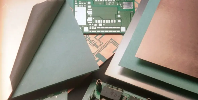
Common PCB Laminate Materials Compared
Standard FR-4
Characteristics:
- Most common and economical
- Tg typically 130-140°C (mid-range available at 170-180°C)
- Dk ~4.3 at 1 MHz, Df ~0.02
- Good mechanical properties
Best For:
- Consumer electronics
- General purpose digital circuits
- Low-cost, high-volume production
High-Tg FR-4
Characteristics:
- Tg of 170°C or higher
- Improved thermal and chemical resistance
- Better dimensional stability at elevated temps
- Slightly higher cost than standard FR-4
Best For:
- Lead-free assembly processes
- Automotive under-hood applications
- Industrial equipment with thermal demands
Polyimide
Characteristics:
- Tg >250°C, excellent thermal stability
- Low CTE, good dimensional stability
- Higher cost than FR-4
- More difficult to process
Best For:
- Aerospace and military applications
- High-reliability medical devices
- Flexible circuits
PTFE-Based (Teflon) Materials
Characteristics:
- Excellent high-frequency properties (Dk 2.1-3.0, very low Df)
- Challenging manufacturing process
- High cost
- Poor mechanical strength
Best For:
- RF and microwave circuits
- Millimeter wave applications
- High-performance antenna systems
Ceramic-Filled Hydrocarbon
Characteristics:
- Moderate cost between FR-4 and PTFE
- Good high-frequency properties
- Better mechanical properties than PTFE
- Easier processing than pure PTFE
Best For:
- Base station antennas
- Automotive radar
- 5G infrastructure
Advanced Considerations in Laminate Selection
Mixed Material Stackups
Modern PCBs often combine multiple laminate types:
- High-speed signal layers on low-loss material
- Power planes on standard FR-4
- Hybrid rigid-flex constructions
Design Challenges:
- CTE mismatch management
- Lamination process compatibility
- Via reliability across material boundaries
Signal Loss Analysis
For high-frequency designs:
- Model insertion loss vs. frequency
- Consider roughness effects on conductor loss
- Evaluate glass weave style impact on signal integrity
Manufacturing Tolerances
Understand material-specific tolerances:
- Dielectric thickness variation
- Copper roughness
- Dk tolerance across frequency
Future Trends in PCB Laminate Technology
Emerging Materials
- Ultra-low loss materials for 5G mmWave
- High thermal conductivity substrates for power electronics
- Environmentally friendly halogen-free materials
- Embedded passive material technologies
Design Integration
- Materials supporting higher component integration
- Substrates enabling 3D packaging
- Advanced materials for HDI (High Density Interconnect) applications
Conclusion
Selecting the optimal PCB laminate material requires careful consideration of electrical, thermal, mechanical, and manufacturing requirements balanced against cost constraints. By systematically evaluating application needs against material properties, designers can make informed choices that ensure reliability while avoiding unnecessary material costs. As electronic systems continue to push performance boundaries, laminate selection becomes increasingly critical to achieving design success.
Remember that material selection should occur early in the design process, as it affects nearly all aspects of the PCB from stackup design to manufacturing process. When in doubt, consult with your PCB fabricator and material suppliers early in the design cycle to validate your material choices and avoid costly redesigns later in the process.


