How to Choose the Right PCB Antenna for Your Wireless Design
Introduction
In the rapidly evolving world of wireless communication, Printed Circuit Board (PCB) antennas have become a popular choice due to their compact size, low cost, and ease of integration. Selecting the right PCB antenna is crucial for ensuring optimal performance in applications such as IoT devices, Wi-Fi modules, Bluetooth-enabled products, and cellular communications.
This article explores key considerations when choosing a PCB antenna, including antenna types, design parameters, performance trade-offs, and practical implementation tips.
1. Understanding PCB Antenna Types
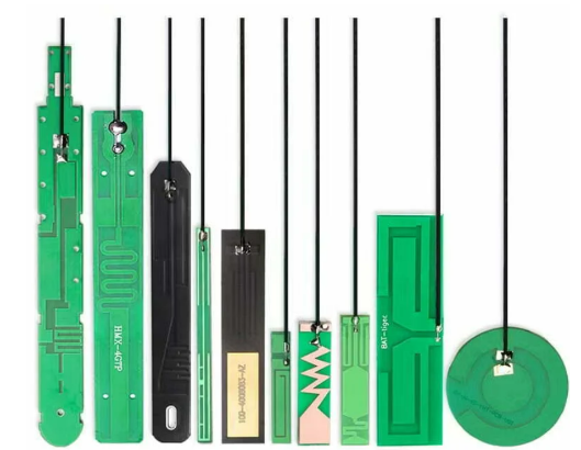
PCB antennas come in various forms, each with distinct advantages and limitations. The most common types include:
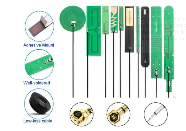
1.1 Trace Antennas (Monopole, Dipole, Inverted-F, Meander Line)
- Monopole Antennas: Require a ground plane and are simple to design but may have limited bandwidth.
- Dipole Antennas: Offer better radiation patterns but need balanced feeding and more space.
- Inverted-F Antennas (IFA): Compact and widely used in Bluetooth/Wi-Fi modules due to their good impedance matching.
- Meander Line Antennas: Reduce physical length by folding the trace, making them suitable for space-constrained designs.
1.2 Patch Antennas
- Consist of a metallic patch on a dielectric substrate over a ground plane.
- Provide directional radiation, making them ideal for applications requiring focused signals (e.g., GPS, RFID).
- Limited bandwidth but highly efficient when properly tuned.
1.3 Planar Inverted-F Antennas (PIFA)
- A variation of IFA with a wider bandwidth and better performance in compact designs.
- Commonly used in smartphones and portable devices.
1.4 Ceramic Chip Antennas
- Small, surface-mount components ideal for ultra-compact designs.
- Require careful impedance matching and PCB layout optimization.
2. Key Selection Criteria
2.1 Frequency Band & Bandwidth
- The antenna must support the desired frequency range (e.g., 2.4 GHz for Bluetooth, 5 GHz for Wi-Fi 6, sub-GHz for LoRa).
- Wider bandwidth antennas (e.g., UWB) are needed for applications requiring multiple frequency channels.
2.2 Radiation Pattern & Gain
- Omnidirectional antennas (e.g., monopoles) are best for general wireless communication.
- Directional antennas (e.g., patch antennas) are suitable for point-to-point links.
- Gain affects signal range but may increase power consumption.
2.3 Size & Form Factor
- Small IoT devices may require compact antennas (e.g., ceramic chip or meander line).
- Larger antennas (e.g., dipoles) offer better performance but may not fit in space-limited designs.
2.4 PCB Material & Layout Considerations
- The dielectric constant (Dk) and thickness of the PCB substrate impact antenna performance.
- Keep antennas away from noisy components (e.g., power supplies, high-speed digital traces).
- Ensure proper ground plane size (especially for monopole antennas).
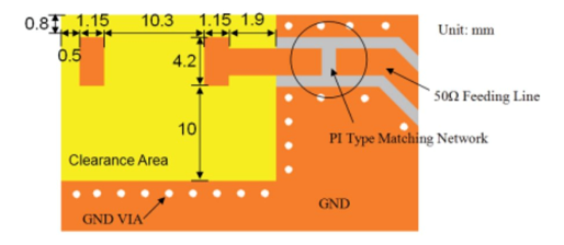
2.5 Matching Network & Tuning
- Antennas often require a matching network (LC circuit) to optimize impedance (typically 50Ω).
- Simulation tools (e.g., ANSYS HFSS, CST) help in tuning before fabrication.
2.6 Regulatory Compliance (FCC, CE, etc.)
- Ensure the antenna meets regulatory standards for radiated power and spurious emissions.
- Pre-certified antenna modules can simplify compliance testing.
3. Performance Trade-offs
- Size vs. Efficiency: Smaller antennas may suffer from lower radiation efficiency.
- Cost vs. Performance: Off-the-shelf chip antennas are cost-effective but may require fine-tuning, while custom-designed antennas offer better performance at higher development costs.
- Integration Complexity: Some antennas (e.g., PIFA) need precise PCB placement, while others (e.g., trace antennas) are easier to implement.
4. Practical Implementation Tips
- Simulate Before Fabrication: Use EM simulation tools to predict antenna behavior.
- Prototype & Test: Verify performance in real-world conditions (e.g., anechoic chamber testing).
- Consider Environmental Factors: Metal enclosures, plastic casings, and nearby components can detune the antenna.
- Use Reference Designs: Many IC manufacturers (e.g., Nordic, TI, Espressif) provide antenna layout guidelines.
5. Conclusion
Choosing the right PCB antenna involves balancing performance, size, cost, and regulatory requirements. By understanding different antenna types, key selection criteria, and practical implementation strategies, engineers can optimize wireless designs for reliability and efficiency.
Whether designing for IoT, consumer electronics, or industrial applications, a well-selected PCB antenna ensures robust wireless connectivity—a critical factor in today’s interconnected world.


