How to implement the PCB design of power modules? What is the principle?
With the rapid development of science and technology, efficient and stable power modules play an indispensable role in various electronic devices. PCB design, as a key link in the research and development of power modules, affects the performance, reliability and stability of power modules. This article will deeply explore the PCB design principles and implementation process of power modules, aiming to provide useful reference for researchers and engineers in related fields.
1.Principles of PCB design of power modules
The main principles of PCB design of power modules include power transmission and heat diffusion. In terms of power transmission, PCB design needs to consider how to effectively convert input power into required voltage and current while improving power efficiency. To ensure heat diffusion, PCB design should optimize the layout of components so that the power module can work stably in a high temperature environment. In addition, good PCB design can also improve the anti-interference performance of the power module and ensure its stable operation.
2.PCB design process of power modules
Graphic design
In the graphic design stage, it is necessary to select the appropriate PCB board and size according to the performance requirements of the power module. Use professional software to draw the circuit diagram of the power module and generate the corresponding PCB wiring diagram.
Circuit board layout
Circuit board layout is a key link in PCB design. During the layout, the positions of various components should be reasonably allocated, taking into account the mutual interference between components, as well as factors such as heat dissipation and signal integrity. In order to improve the performance of the power module, it is also necessary to follow the “3W” principle (that is, the line width, line spacing, and component spacing are all greater than 3 times the minimum operating wavelength) to reduce electromagnetic interference.
Parameter setting
During the parameter setting stage, it is necessary to set reasonable parameters for each component, such as resistance value, capacitance, filter response time, etc. The parameter setting needs to be adjusted according to the actual needs and performance requirements of the power module to ensure that the power module achieves the best performance under specific conditions.
3.Power module PCB design principles
Stability principle
The stability principle is the primary consideration for power module PCB design. PCB design should ensure that the power module can work stably in various environments, including high temperature, low temperature, high humidity, salt spray and other harsh environments. To improve stability, the following measures can be taken: select high-quality components; reasonably set protection circuits; optimize thermal design to reduce the impact of the environment on the performance of the power module.
Anti-interference principle
The power module will be subject to electromagnetic interference from various interference sources during work, such as power grid fluctuations, lightning, electronic equipment, etc. Therefore, PCB design should follow the principle of anti-interference and take effective anti-interference measures to reduce the impact of electromagnetic interference on the performance of the power module. For example, reasonably plan the layout of the power line and the ground line; use filtering elements; shield key components and signal lines, etc.
Principle of thermal stability
The power module will generate a lot of heat during operation, and temperature fluctuations will have a serious impact on the performance of the power module. Therefore, PCB design should follow the principle of thermal stability, and improve the heat dissipation capacity of the power module by optimizing the layout of components, selecting materials with good thermal conductivity, and reasonably setting up heat dissipation channels, so as to ensure that it maintains stable performance within the operating temperature range.
[Case Analysis]
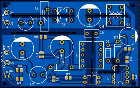
Take the PCB design of a 5V DC power module as an example, its output power is 100W and the input voltage range is 90V-260V. According to performance requirements, the power module needs to have high efficiency, high stability and excellent anti-interference performance. In PCB design, we took the following measures:
Select high-quality PCB materials, such as FR4, CEM-1, etc., to have good electrical and mechanical properties.
Arrange components reasonably to isolate the high-voltage and low-voltage parts to reduce mutual interference; at the same time, follow the “3W” principle to reduce electromagnetic interference between lines.
Add appropriate filtering components, such as power filters, magnetic rings, etc., to weaken the impact of power grid fluctuations and electromagnetic interference on the performance of the power module.
Through thermal design optimization, select materials with good thermal conductivity, set up reasonable heat dissipation channels, and ensure that the power module can still work stably in a high temperature environment.
After the above measures, we successfully designed a 5V DC power module with high efficiency, stability and strong anti-interference, and verified the effectiveness of PCB design in practical applications.
[Conclusion]
This article deeply explores the PCB design principles and implementation process of the power module. By understanding the principles and processes of PCB design, and the necessity of designing in accordance with the principles of stability, anti-interference and thermal stability.