How to Select PCB Materials and Laminates for Manufacturing
Introduction
Printed Circuit Board (PCB) manufacturing begins with one critical decision: selecting the appropriate base materials. The choice of PCB substrate and laminate materials significantly impacts the board’s performance, reliability, manufacturability, and cost. With numerous options available in the market—from standard FR-4 to high-frequency specialty materials—designers must carefully evaluate their requirements against material properties.
This comprehensive guide examines the key considerations for selecting PCB materials and laminates, covering electrical, mechanical, thermal, and economic factors that influence material selection for various applications.
1. Understanding PCB Material Composition
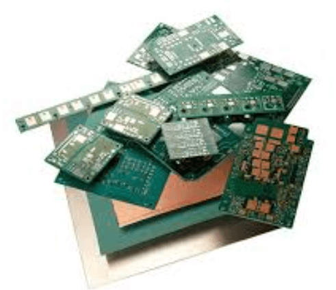
1.1 Basic Structure of PCB Laminates
PCB laminates consist of three primary components:
- Reinforcement material (typically woven glass fiber)
- Resin system (such as epoxy, polyimide, or PTFE)
- Conductive foil (usually copper)
The combination and treatment of these elements determine the laminate’s properties. For multilayer boards, prepreg (pre-impregnated) materials bond the layers together during lamination.
1.2 Common Material Classifications
- FR-4: The industry standard, flame-retardant epoxy-glass laminate
- High-Tg FR-4: Enhanced thermal performance versions
- Polyimide: For high-temperature or flexible applications
- PTFE/Rogers materials: For high-frequency/RF applications
- Metal-core: For thermal management (aluminum or copper base)
- Ceramic-filled: For specialized thermal/mechanical needs
2. Key Selection Criteria for PCB Materials
2.1 Electrical Properties
Dielectric Constant (Dk or εr):
- Affects signal propagation speed and impedance
- Lower Dk (2.2-3.5) preferred for high-speed designs
- Standard FR-4: ~4.3 at 1 MHz, varies with frequency
Dissipation Factor (Df or tan δ):
- Measures dielectric loss
- Critical for high-frequency applications (>1 GHz)
- Standard FR-4: ~0.02, high-performance materials: <0.005
Surface and Volume Resistivity:
- Important for high-voltage applications
- Moisture absorption affects these properties
Dielectric Strength:
- Voltage breakdown threshold
- Typically 800-1500 V/mil for most laminates
2.2 Thermal Properties
Glass Transition Temperature (Tg):
- Temperature where material changes from rigid to soft
- Standard FR-4: 130-140°C, High-Tg: 170-180°C
- Higher Tg improves thermal reliability
Decomposition Temperature (Td):
- When material chemically decomposes
- Should be significantly higher than soldering temperatures
Coefficient of Thermal Expansion (CTE):
- X/Y axis: Typically 12-16 ppm/°C (matches copper)
- Z-axis: Higher values (50-70 ppm/°C) can cause via reliability issues
- Low CTE materials reduce thermal stress
Thermal Conductivity:
- Standard FR-4: ~0.3 W/mK
- Specialized materials can reach 1-4 W/mK for better heat dissipation
2.3 Mechanical Properties
Flexural Strength:
- Important for boards with heavy components
- Typically 400-700 MPa for FR-4
Peel Strength:
- Copper adhesion measurement
- Should exceed 1 N/mm for reliability
Moisture Absorption:
- Affects electrical and thermal properties
- Standard FR-4: ~0.1-0.2%, polyimide: ~0.4-0.8%
Dimensional Stability:
- Critical for fine-pitch components
- Typically <0.1% change after processing
2.4 Manufacturing Considerations
Drillability:
- Glass weave can affect drill wear and hole quality
- Some high-frequency materials are softer and require special drill bits
Lamination Parameters:
- Temperature and pressure requirements vary
- Some materials need special lamination cycles
Chemical Resistance:
- Must withstand etching, plating, and cleaning processes
- Some high-frequency materials are sensitive to certain chemicals
Availability and Lead Times:
- Standard materials have short lead times
- Specialty materials may require weeks for procurement
3. Material Selection by Application
3.1 Consumer Electronics
- Typical choice: Standard FR-4
- Considerations: Cost, basic reliability, RoHS compliance
- Variations: Halogen-free versions for environmental requirements
3.2 Automotive Electronics
- Typical choice: High-Tg FR-4 or polyimide
- Considerations: Temperature cycling resistance, vibration tolerance
- Special requirements: AEC-Q200 qualification for critical components
3.3 High-Speed Digital
- Typical choice: Low-loss FR-4 or mid-performance materials
- Key parameters: Stable Dk across frequency, low Df
- Examples: Isola 370HR, Panasonic Megtron 6
3.4 RF/Microwave
- Typical choice: PTFE-based or ceramic-filled laminates
- Key parameters: Ultra-low Df, consistent Dk
- Examples: Rogers RO4000 series, Taconic RF-35
3.5 High-Power Electronics
- Typical choice: Metal-core or ceramic substrates
- Key parameters: Thermal conductivity, dielectric strength
- Examples: Bergquist thermal clad, Rogers curamik
3.6 Flexible Circuits
- Typical choice: Polyimide films
- Considerations: Dynamic flex requirements, bend radius
- Variations: Adhesive-less constructions for thin designs
4. Cost Considerations
Material costs can vary dramatically:
- Standard FR-4: $2-5/sq.ft.
- Mid-performance: $5-15/sq.ft.
- High-frequency: $20-200+/sq.ft.
Cost drivers include:
- Raw material scarcity (e.g., PTFE)
- Processing complexity
- Volume pricing
- Geographic supply chains
Designers should balance performance needs with budget constraints, considering:
- Total cost of ownership (including field failures)
- Assembly yields
- Qualification/testing expenses
5. Emerging Material Trends
5.1 Low-Loss Materials for 5G
Materials optimized for mmWave frequencies (24-100 GHz) with:
- Ultra-low Df (<0.002 at 10 GHz)
- Tight Dk tolerances (±0.05)
5.2 High-Thermal-Conductivity Substrates
New ceramic-filled and composite materials offering:
- 1-4 W/mK conductivity
- CTE matching semiconductors
5.3 Sustainable Materials
Eco-friendly alternatives featuring:
- Bio-based resins
- Recyclable constructions
- Halogen-free formulations
5.4 Embedded Component Materials
Specialized dielectrics for:
- Passive component integration
- Semiconductor embedding
- Heterogeneous integration
6. Practical Selection Methodology
- Define Requirements:
- Electrical (frequency, loss tolerance)
- Thermal (operating temps, power dissipation)
- Mechanical (size constraints, flex needs)
- Environmental (humidity, chemicals)
- Regulatory (safety, emissions)
- Screen Materials:
- Eliminate options that don’t meet critical needs
- Create shortlist of 2-3 candidates
- Evaluate Tradeoffs:
- Performance vs. cost
- Availability vs. lead time
- Manufacturability vs. design complexity
- Prototype and Test:
- Build test coupons for critical parameters
- Verify manufacturability with your PCB vendor
- Conduct accelerated life testing
- Qualify and Document:
- Formalize material specifications
- Document approved vendors
- Establish inspection criteria
7. Working with PCB Manufacturers
Effective material selection requires collaboration with fabrication partners:
- Provide complete specifications: Include all critical parameters
- Discuss alternatives: Manufacturers may know equivalent materials
- Understand process capabilities: Not all shops handle specialty materials
- Review test data: Request material property reports
- Consider panel utilization: Some materials have size constraints
Conclusion
Selecting the optimal PCB material requires balancing multiple technical requirements with practical manufacturing considerations and cost constraints. While FR-4 serves adequately for many applications, advancing technologies increasingly demand specialized materials with tailored properties.
By systematically evaluating electrical, thermal, mechanical, and manufacturing requirements against available material options, designers can make informed selections that ensure reliability while controlling costs. As material technology continues evolving—particularly for high-frequency, high-power, and sustainable applications—staying informed about new developments remains essential for optimal PCB design and manufacturing.


