How to Test Circuit Boards: A Comprehensive Guide
Introduction
Circuit boards are the backbone of modern electronics, found in everything from smartphones and computers to medical devices and industrial machinery. Ensuring their proper functionality is crucial, as even minor defects can lead to system failures. Testing circuit boards is a critical step in manufacturing, troubleshooting, and repair processes. This guide explores various methods for testing circuit boards, including visual inspection, automated testing, functional testing, and advanced diagnostic techniques.
1. Visual Inspection
Before applying any electrical tests, a thorough visual inspection should be conducted to identify obvious defects.
Steps for Visual Inspection:
- Check for Physical Damage:
- Look for cracks, scratches, or broken traces on the PCB.
- Inspect solder joints for cold solder (dull or grainy appearance) or solder bridges (unintended connections).
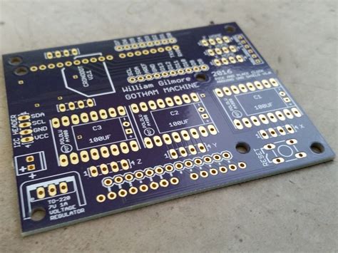
- Verify Component Placement:
- Ensure all components (resistors, capacitors, ICs) are correctly placed and aligned.
- Check for missing or misoriented parts (e.g., diodes or polarized capacitors installed backward).
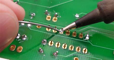
- Examine Soldering Quality:
- Poor soldering can lead to open or short circuits.
- Use a magnifying glass or microscope for fine-pitch components.
- Look for Contamination:
- Dust, flux residue, or moisture can cause leakage currents or corrosion.
Tools for Visual Inspection:
- Magnifying Glass / Microscope – For detailed examination.
- Bright Lighting – Helps spot defects more easily.
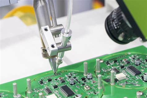
- Automated Optical Inspection (AOI) – Used in manufacturing for high-speed PCB inspection.
2. Continuity Testing (Using a Multimeter
A multimeter is essential for checking electrical continuity and resistance.
Steps for Continuity Testing:
- Set the Multimeter to Continuity Mode (Ω or Beep Mode).
- Test Power and Ground Connections:
- Place one probe on a power rail and the other on ground to check for shorts.
- Check Signal Traces:
- Verify that traces are intact (no open circuits).
- Test Component Connections:
- Ensure resistors, capacitors, and diodes are properly connected.
Common Issues Detected:
- Open Circuits (broken traces).
- Short Circuits (unintended connections).
- Incorrect Resistance Values (faulty resistors).
3. Power-On Testing (Voltage and Current Checks)
After confirming no shorts, apply power and measure voltages.
Steps for Power-On Testing:
- Use a Bench Power Supply with Current Limiting (to prevent damage).
- Check Voltage Levels:
- Verify VCC, GND, and other critical voltages (e.g., 3.3V, 5V, 12V).
- Measure Current Draw:
- Abnormal current may indicate a short or faulty component.
- Test Voltage Regulators:
- Ensure they provide correct output voltages.
Tools Needed:
- Digital Multimeter (DMM)
- Oscilloscope (for dynamic signal analysis)
4. Functional Testing
Functional testing ensures the PCB performs as intended in real-world conditions.
Methods:
- Input/Output Testing:
- Apply known inputs and verify expected outputs (e.g., pressing buttons, reading sensors).
- Firmware Validation:
- If the PCB has a microcontroller, flash test firmware to verify operation.
- Communication Tests:
- Check UART, I2C, SPI, or USB interfaces for proper data transfer.
Automated Functional Test (ATE):
- In-Circuit Test (ICT): Uses a bed-of-nails fixture to test multiple points simultaneously.
- Flying Probe Test: Moves probes dynamically to test PCBs without fixtures.
5. Advanced Testing Techniques
For complex PCBs, advanced methods may be required.
A. In-Circuit Testing (ICT)
- Tests individual components (resistors, capacitors, transistors) while powered off.
- Detects wrong values, open/short circuits.
B. Boundary Scan Testing (JTAG)
- Uses IEEE 1149.1 standard to test ICs and interconnects.
- Ideal for high-density boards with BGA chips.
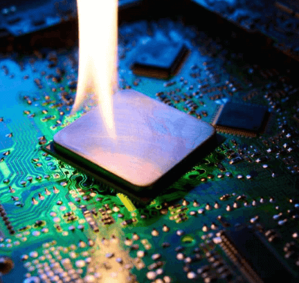
C. Thermal Imaging
- Infrared Cameras detect overheating components (e.g., failing regulators or shorted traces).
D. X-Ray Inspection
- Used for hidden defects (e.g., BGA solder joints, internal PCB layers).
6. Environmental and Stress Testing
To ensure reliability, PCBs may undergo:
- Temperature Cycling (exposing to extreme hot/cold).
- Vibration Testing (for automotive/military applications).
- Humidity Testing (to check for corrosion risks).
7. Debugging and Troubleshooting
If a PCB fails testing:
- Isolate the Problem:
- Divide the circuit into sections (power, analog, digital).
- Check Signal Integrity:
- Use an oscilloscope to analyze waveforms.
- Replace Suspect Components:
- Swap ICs, capacitors, or connectors to identify faults.
Conclusion
Testing circuit boards involves multiple stages—from visual checks to advanced diagnostics—to ensure reliability and functionality. By following structured testing methods, engineers and technicians can detect defects early, reduce failures, and improve product quality. Whether using simple multimeters or automated test systems, a thorough approach to PCB testing is essential for successful electronics manufacturing and repair.
By mastering these techniques, professionals can efficiently diagnose and fix issues, ensuring robust and long-lasting electronic devices.
Final Tips for Effective PCB Testing:
✅ Always start with a visual inspection.
✅ Use multimeters and oscilloscopes for basic checks.
✅ Apply power cautiously to avoid damage.
✅ Consider automated testing for high-volume production.
✅ Perform environmental tests for critical applications.
By following this guide, you can systematically test and validate circuit boards, ensuring optimal performance and reliability.