How to Test PCB Grounding: A Comprehensive Guide
Introduction to PCB Grounding
Proper grounding is one of the most critical aspects of printed circuit board (PCB) design and functionality. Grounding provides a reference voltage level for all components on the board, serves as a return path for currents, and helps shield sensitive circuits from electromagnetic interference (EMI). When grounding is implemented incorrectly, it can lead to numerous problems including noise coupling, signal integrity issues, and even complete circuit failure.
Testing PCB grounding is essential to ensure your board operates as intended, meets electromagnetic compatibility (EMC) requirements, and maintains reliability throughout its lifecycle. This 2000-word guide will explore various methods for testing PCB grounding, from basic continuity checks to advanced impedance measurements.
Testing PCB grounding is essential to ensure your board operates as intended, meets electromagnetic compatibility (EMC) requirements, and maintains reliability throughout its lifecycle. This 2000-word guide will explore various methods for testing PCB grounding, from basic continuity checks to advanced impedance measurements.
Understanding Grounding Systems in PCBs
Before testing grounding, it’s important to understand the different grounding approaches used in PCBs:
- Single-point grounding: All ground connections meet at one physical location
- Multi-point grounding: Components connect to the nearest ground point
- Hybrid grounding: Combines aspects of both single-point and multi-point
- Split ground planes: Separate analog and digital grounds that connect at one point
The grounding strategy affects how you should test the connections. For instance, single-point systems require verification that no alternate ground paths exist, while multi-point systems need confirmation of low impedance between all ground points.
Essential Tools for Testing PCB Grounding
To properly test PCB grounding, you’ll need several tools:
- Multimeter (digital preferred)
- For continuity checks and resistance measurements
- Minimum requirements: 3.5 digit display, relative mode
- Ohmmeter
- For low-resistance measurements (milliohm range)
- 4-wire Kelvin measurement capability is ideal
- Oscilloscope
- For observing ground noise and transients
- Bandwidth should exceed your signal frequencies
- Network analyzer (for advanced testing)
- Measures ground plane impedance vs frequency
- Typically expensive bench equipment
- Current probe
- For measuring ground return currents
- Both AC and DC capable models available
- Spectrum analyzer
- For EMI testing related to ground issues
- Helps identify ground loop problems
Basic Grounding Tests
1. Continuity Testing
The most fundamental grounding test verifies electrical continuity between all ground points.
Procedure:
- Power off the PCB and discharge all capacitors
- Set multimeter to continuity/ohms mode
- Select a reference ground point (usually the power connector ground)
- Touch one probe to the reference, check all other ground points
- Verify near-zero resistance (typically <1Ω)
Interpretation:
- Expected: Low resistance between all ground points
- Problem: Open circuit (infinite resistance) indicates broken connection
- Caution: Some designs intentionally have isolated ground sections
2. Resistance Measurement
More precise than continuity testing, resistance measurement quantifies ground path quality.
Procedure:
- Use 4-wire Kelvin measurement if available
- Measure between various ground points
- Record values at multiple locations
Acceptable Values:
- Within a ground plane: <10mΩ
- Between board sections: <100mΩ
- Through vias/connectors: <500mΩ
3. Insulation Testing
Verifies no unwanted connections exist between ground and other nets.
Procedure:
- Set meter to high-resistance mode (megohms)
- Measure between ground and:
- Power rails
- Signal traces
- Chassis connections
- Verify no leakage paths
Expected Results:
- >1MΩ for most connections
- Exceptions: Designed-in pull-up/down resistors
Advanced Grounding Tests
4. Ground Impedance Measurement
AC impedance is more important than DC resistance for high-frequency performance.
Methods:
A. Network analyzer method:
- Connect analyzer between ground points
- Sweep frequency (typically 1kHz-1GHz)
- Plot impedance vs frequency
B. Oscilloscope method:
- Inject known current pulse
- Measure voltage response
- Calculate impedance (Z=V/I)
Acceptable Values:
- <100mΩ up to 100MHz
- <1Ω up to 1GHz (for high-speed designs)
5. Ground Noise Measurement
Excessive noise indicates grounding problems.
Procedure:
- Power on the PCB
- Connect oscilloscope probe to ground
- Use shortest possible ground lead
- Observe noise characteristics:
- Amplitude
- Frequency components
- Transient responses
Typical Problems:
- Digital switching noise in analog grounds
- 50/60Hz hum from ground loops
- High-frequency ringing indicating impedance mismatches
6. Current Distribution Analysis
Verifies ground currents flow as intended.
Procedure:
- Use current probe or shunt resistor
- Measure current at various ground points
- Compare with expected distribution
Common Issues:
- Uneven current distribution causing localized heating
- High current density through small traces
- Unexpected current paths creating ground loops
Specialized Grounding Tests
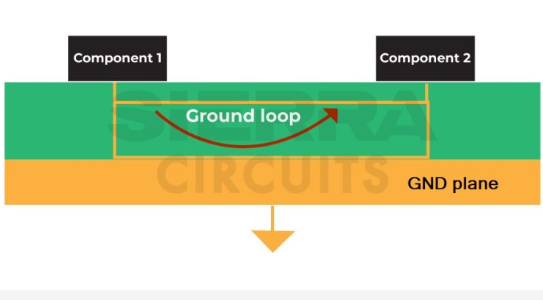
7. Ground Loop Testing
Ground loops occur when multiple current return paths exist.
Detection Methods:
- Measure voltage differences between ground points
- Look for 50/60Hz noise in sensitive circuits
- Use spectrum analyzer to identify characteristic frequencies
8. Transfer Impedance Measurement
Important for evaluating ground plane effectiveness.
Procedure:
- Inject current at one point
- Measure voltage at another point
- Calculate transfer impedance (Zt=V/I)
Significance:
- Lower Zt indicates better high-frequency performance
- Reveals effectiveness of ground plane as shield
9. Thermal Imaging
Identifies grounding problems through heat patterns.
Application:
- Locate high-resistance ground connections
- Find current crowding areas
- Verify adequate current carrying capacity
Testing Grounding in Mixed-Signal PCBs
Mixed-signal designs with both analog and digital sections require special grounding tests:
- Cross-coupling measurement:
- Inject digital signal
- Measure coupled noise in analog ground
- Isolation verification:
- Confirm specified separation between ground sections
- Check single-point connection (if used)
- Return path analysis:
- Verify digital currents don’t flow through analog ground
- Ensure proper partitioning
EMI/EMC Grounding Tests
Proper grounding is essential for electromagnetic compliance:
- Radiated emissions testing:
- Correlate emissions spikes with grounding issues
- Conducted emissions testing:
- Identify ground-related noise on power lines
- Immunity testing:
- Monitor ground stability during EMC tests
- Note susceptibility to external interference
Best Practices for Ground Testing
- Test at multiple frequencies – Ground performance varies with frequency
- Check under load conditions – Ground behavior changes with current
- Verify at temperature extremes – Thermal effects impact connections
- Test prototype and production boards – Manufacturing variations matter
- Document baseline measurements – For future comparison and troubleshooting
Common PCB Grounding Problems and How to Detect Them
- Insufficient Ground Plane
- Symptoms: High impedance, excessive noise
- Detection: Impedance measurement, thermal imaging
- Ground Loops
- Symptoms: Hum, interference between sections
- Detection: Voltage differences, spectrum analysis
- Star Ground Not Implemented Correctly
- Symptoms: Noise coupling between circuits
- Detection: Current distribution analysis
- Poor High-Frequency Grounding
- Symptoms: Signal integrity issues at high speeds
- Detection: Impedance vs frequency plots
- Corroded or Damaged Ground Connections
- Symptoms: Intermittent operation, higher resistance
- Detection: Continuity testing, visual inspection
Conclusion
Thorough testing of PCB grounding is essential for reliable circuit operation. By implementing the methods described – from basic continuity checks to advanced impedance measurements – you can identify and correct grounding issues before they cause problems in your design. Remember that grounding requirements vary significantly depending on application, frequency range, and noise sensitivity, so always tailor your testing approach to your specific design needs.
Regular grounding verification should be part of your standard PCB validation process, from initial prototyping through production testing. The time invested in proper ground testing will pay dividends through improved product reliability, reduced EMI issues, and easier compliance with regulatory requirements.
By mastering these PCB grounding testing techniques, you’ll be better equipped to design boards that perform as intended in real-world conditions, with robust grounding that ensures signal integrity and minimizes electromagnetic interference.