How to Troubleshoot a Circuit Board: A Step-by-Step Guide
Introduction
Circuit boards are the backbone of modern electronics, found in everything from smartphones to industrial machinery. When a circuit board malfunctions, it can lead to system failures, data loss, or even safety hazards. Troubleshooting a circuit board requires a systematic approach, combining technical knowledge, diagnostic tools, and logical problem-solving skills.
This guide provides a comprehensive step-by-step process for troubleshooting circuit boards, covering common issues, essential tools, and best practices to identify and resolve faults efficiently.
Step 1: Understand the Circuit Board
Before troubleshooting, familiarize yourself with the circuit board’s design and functionality:
- Review the Schematic Diagram – If available, study the board’s schematic to understand component connections, power rails, and signal paths.
- Identify Key Components – Locate critical parts such as microcontrollers, voltage regulators, capacitors, resistors, and connectors.
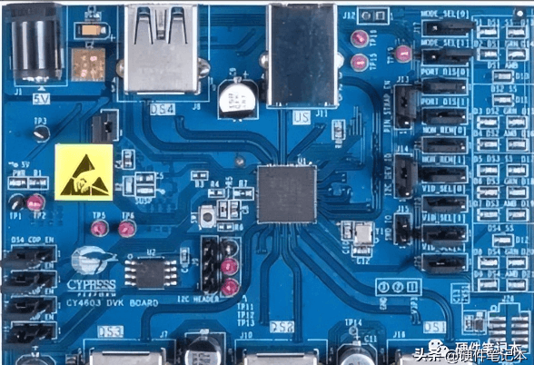
- Check the PCB Layout – Look for visible traces, vias, and potential points of failure (e.g., burnt areas or damaged solder joints).
Step 2: Perform a Visual Inspection
Many circuit board issues can be detected visually:
- Look for Physical Damage –
- Burnt or discolored components (indicating overheating).
- Cracked or broken traces.
- Bulging or leaking capacitors.
- Cold or cracked solder joints (use a magnifying glass if needed).
- Check for Short Circuits –
- Examine solder bridges between pins.
- Look for unintended metal debris causing shorts.
- Inspect Connectors & Wiring –
- Loose or corroded connectors.
- Damaged cables or broken wires.
Step 3: Test Power Supply Issues
A faulty power supply is a common cause of circuit board failures:
- Measure Input Voltage –
- Use a multimeter to verify the input voltage matches specifications.
- Check for fluctuations or drops.
- Test Voltage Regulators –
- Ensure regulators (e.g., 7805 for +5V) output the correct voltage.
- Look for overheating regulators (may indicate a short or overload).
- Check Power Rails –
- Verify voltages at different points (e.g., VCC, GND) using the schematic.
- Look for unexpected voltage drops across traces or components.
Step 4: Check for Shorts & Open Circuits
- Continuity Test –
- Use a multimeter in continuity mode to check for open traces or disconnected components.
- Test between ground and power lines to detect unexpected shorts.
- Resistance Measurement –
- Measure resistance across suspicious traces or components.
- A near-zero resistance may indicate a short.
- Isolate Faulty Sections –
- Disconnect power and remove suspect components (e.g., ICs) to isolate the issue.
Step 5: Test Individual Components
Faulty components often cause circuit malfunctions:
A. Passive Components (Resistors, Capacitors, Inductors)
- Resistors – Measure resistance; a significantly different value indicates failure.
- Capacitors – Use an ESR meter or capacitance meter; bulging or leaking caps should be replaced.
- Diodes & Transistors – Test with a multimeter in diode mode; check forward/reverse bias behavior.
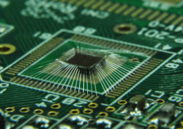
B. Active Components (ICs, Microcontrollers)
- Check Datasheets – Verify pin voltages and signal behavior.
- Use an Oscilloscope – Probe clock signals, data lines, and communication buses (I2C, SPI, UART).
- Look for Overheating – Excess heat may indicate a shorted IC.
C. Connectors & Switches
- Test continuity and mechanical integrity.
- Clean oxidized contacts with isopropyl alcohol.
Step 6: Signal Tracing & Functional Testing
If the board powers on but behaves erratically:
- Oscilloscope Analysis –
- Check clock signals for correct frequency and stability.
- Probe digital signals (e.g., PWM, serial data) for abnormalities.
- Logic Analyzer –
- Useful for debugging digital communication (e.g., I2C, SPI issues).
- Compare with a Working Board –
- If possible, compare signals between a faulty and functional board.
Step 7: Firmware & Software Checks
For microcontroller-based boards:
- Re-flash Firmware – Corrupt firmware can cause malfunctions.
- Debug via Serial Output – Check UART logs for error messages.
- Review Code – Look for infinite loops or incorrect peripheral configurations.
Step 8: Environmental & Interference Issues
Some failures are caused by external factors:
- EMI/RFI Noise –
- Check for interference from motors, wireless signals, or power lines.
- Use shielding or ferrite beads if necessary.
- Thermal Stress –
- Overheating components may fail under load; consider adding heatsinks.
- Vibration & Mechanical Stress –
- Loose components may need reinforcement with adhesive.
Step 9: Repair & Replacement
Once the fault is identified:
- Replace Defective Components – Desolder and install new parts.
- Repair Broken Traces – Use jumper wires or conductive epoxy.
- Re-solder Weak Joints – Apply fresh solder to cold joints.
Step 10: Final Verification
Before reassembling:
- Power-On Test – Verify correct operation.
- Stress Test – Run the board under load to ensure stability.
- Document Findings – Record troubleshooting steps for future reference.
Conclusion
Troubleshooting a circuit board requires patience, methodical testing, and the right tools. By following this structured approach—visual inspection, power checks, component testing, and signal analysis—you can efficiently diagnose and repair most circuit board issues. Regular maintenance and proper handling can also prevent future failures, ensuring long-term reliability.
With practice, troubleshooting becomes an intuitive skill, enabling you to restore functionality to even the most complex electronic systems.