How to Troubleshoot PCB: A Comprehensive Guide
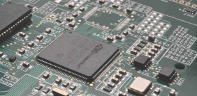
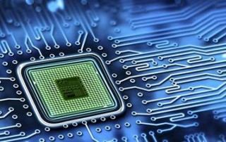
Printed Circuit Boards (PCBs) are the backbone of modern electronics, found in everything from smartphones to industrial machinery. However, even well-designed PCBs can encounter issues during manufacturing, testing, or operation. Effective troubleshooting is essential to identify and resolve these problems efficiently. This guide provides a structured approach to PCB troubleshooting, covering common issues, diagnostic techniques, and repair methods.
1. Understanding Common PCB Problems
Before diving into troubleshooting, it’s crucial to recognize the most frequent PCB issues:
1.1. Short Circuits
- Symptoms: Overheating, burnt components, unexpected power drainage.
- Causes: Solder bridges, incorrect wiring, damaged traces, or component misplacement.
1.2. Open Circuits
- Symptoms: No power, intermittent connections, non-functional circuits.
- Causes: Broken traces, cold solder joints, or disconnected components.
1.3. Component Failures
- Symptoms: Malfunctioning or non-responsive sections of the PCB.
- Causes: Overheating, incorrect voltage, manufacturing defects, or aging.
1.4. Poor Soldering
- Symptoms: Intermittent connectivity, unstable performance.
- Causes: Insufficient solder, cold joints, or excessive solder causing bridges.
1.5. Signal Integrity Issues
- Symptoms: Noise, crosstalk, data corruption.
- Causes: Poor PCB layout, improper grounding, or EMI interference.
1.6. Power Supply Problems
- Symptoms: Voltage drops, unstable operation, failure to power on.
- Causes: Faulty regulators, incorrect power input, or damaged capacitors.
2. Essential Tools for PCB Troubleshooting
Having the right tools is critical for effective debugging:
- Multimeter – Measures voltage, current, and resistance.
- Oscilloscope – Analyzes signal integrity and waveforms.
- Logic Analyzer – Debugs digital circuits.
- Thermal Camera – Detects overheating components.
- Magnifying Glass/Microscope – Inspects solder joints and tiny components.
- Soldering Iron & Desoldering Tools – For repairs and rework.
- PCB Schematic & Layout Files – Essential for tracing connections.
3. Step-by-Step PCB Troubleshooting Process
Follow this systematic approach to diagnose and fix PCB issues:
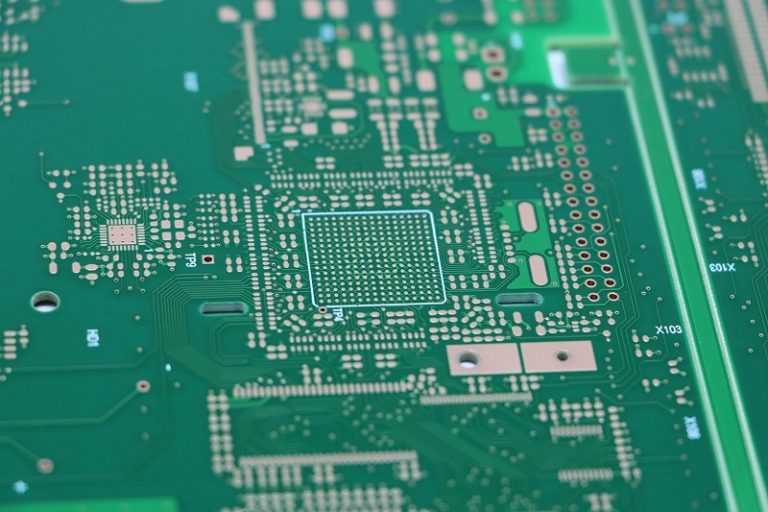
3.1. Visual Inspection
- Check for Obvious Defects: Look for burnt components, broken traces, or solder bridges.
- Inspect Soldering: Ensure no cold joints, insufficient solder, or unintended connections.
- Examine Components: Verify correct placement and orientation (e.g., polarized capacitors, diodes).
3.2. Power Supply Check
- Measure Input Voltage: Confirm the PCB receives the correct voltage.
- Test Regulators & Converters: Ensure stable output voltages.
- Check for Shorts: Use a multimeter in continuity mode to detect unintended connections.
3.3. Signal Tracing
- Follow the Schematic: Trace signals from input to output to identify where they fail.
- Use an Oscilloscope: Verify signal integrity at critical points (e.g., clock signals, data lines).
- Check Ground Connections: Poor grounding can cause noise and instability.
3.4. Component Testing
- Test Diodes & Transistors: Use a multimeter in diode mode.
- Check Capacitors & Resistors: Measure values and look for signs of leakage or damage.
- Inspect ICs: Look for overheating, incorrect logic levels, or missing signals.
3.5. Functional Testing
- Isolate Sections: Disconnect non-essential circuits to narrow down the issue.
- Use Diagnostic Software (if applicable): Many modern PCBs have built-in self-test features.
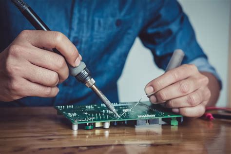
3.6. Repair & Rework
- Fix Broken Traces: Use jumper wires or conductive ink.
- Re-solder Faulty Joints: Ensure proper solder flow and adhesion.
- Replace Defective Components: Desolder and install new parts carefully.
4. Advanced Troubleshooting Techniques
For complex PCBs, additional methods may be necessary:
4.1. Thermal Imaging
- Helps detect overheating components that may indicate short circuits or failing parts.
4.2. X-Ray Inspection
- Useful for multilayer PCBs to identify hidden defects like via cracks or internal shorts.
4.3. Boundary Scan Testing (JTAG)
- Tests digital ICs by scanning input/output states without physical probes.
4.4. Signal Integrity Analysis
- Uses high-speed oscilloscopes to check for reflections, crosstalk, or impedance mismatches.
5. Preventing Future PCB Issues
Proactive measures reduce troubleshooting efforts:
- Follow Design Best Practices: Proper grounding, trace spacing, and component placement.
- Perform Design Rule Checks (DRC): Ensures manufacturability and reduces errors.
- Use Quality Components: Avoid counterfeit or substandard parts.
- Implement Proper Cooling: Prevents overheating-related failures.
- Conduct Thorough Testing: Before mass production, perform functional and stress tests.
6. Conclusion
Troubleshooting PCBs requires a methodical approach, combining visual inspection, electrical testing, and signal analysis. By understanding common failure modes and using the right tools, engineers and technicians can efficiently diagnose and repair PCB issues. Additionally, adhering to best practices in design and manufacturing minimizes future problems, ensuring reliable and long-lasting electronic systems.
Whether you’re a hobbyist or a professional, mastering PCB troubleshooting enhances your ability to maintain and repair electronic devices effectively. With practice and patience, even complex PCB issues can be resolved systematically.