Impedance Control in PCB Design: Principles, Techniques, and Best Practices
Introduction
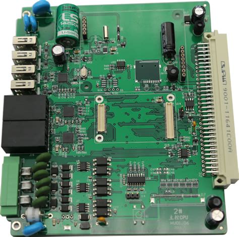
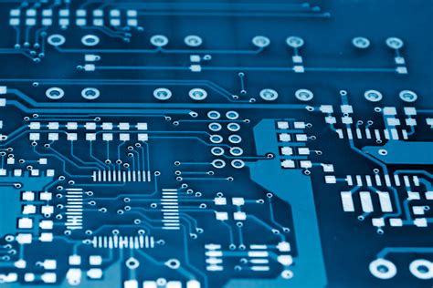
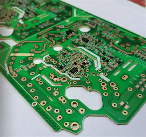
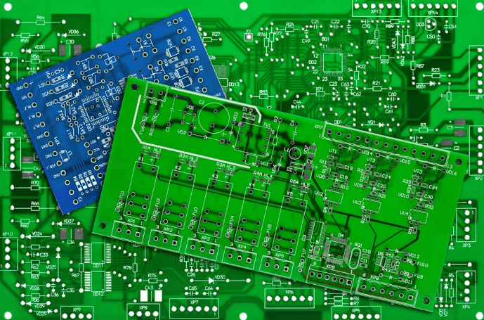
Impedance control is a critical aspect of modern printed circuit board (PCB) design, especially in high-speed digital and high-frequency analog applications. As signal speeds increase, maintaining consistent impedance across transmission lines becomes essential to ensure signal integrity, minimize reflections, and reduce electromagnetic interference (EMI). This article explores the fundamentals of impedance control, its importance, calculation methods, manufacturing considerations, and best practices for achieving optimal PCB performance.
1. Understanding Impedance in PCBs
1.1 What is Impedance?
Impedance (Z) is the total opposition a circuit presents to alternating current (AC), combining resistance (R), inductance (L), and capacitance (C). In PCB transmission lines, impedance determines how signals propagate and interact with the board’s conductive paths.
1.2 Types of Impedance in PCBs
- Characteristic Impedance (Z₀): The impedance of a transmission line in an ideal, lossless scenario. It depends on trace geometry, dielectric material, and surrounding structures.
- Differential Impedance (Zdiff): The impedance between two paired traces carrying differential signals (e.g., USB, HDMI).
- Common-Mode Impedance (Zcm): The impedance of two traces relative to a common reference (e.g., ground).
1.3 Why Impedance Control Matters
- Signal Integrity: Mismatched impedance causes reflections, leading to signal distortion.
- High-Speed Design: Modern interfaces (PCIe, DDR, Ethernet) require tight impedance tolerances (±10% or better).
- EMI Reduction: Controlled impedance minimizes unwanted radiation and crosstalk.
2. Factors Affecting PCB Impedance
Several key factors influence impedance in PCB traces:
2.1 Trace Geometry
- Width (W): Wider traces lower impedance; narrower traces increase it.
- Thickness (T): Thicker copper increases capacitance, reducing impedance.
- Spacing (S): Affects differential impedance in paired traces.
2.2 Dielectric Material
- Dielectric Constant (Dk or εr): Lower εr materials (e.g., Rogers, PTFE) reduce signal loss and allow better impedance control.
- Thickness (H): Thicker dielectrics increase impedance.
2.3 Reference Planes
- A solid ground or power plane beneath the trace helps maintain consistent impedance by providing a return path.
2.4 Frequency Effects
- At higher frequencies, skin effect and dielectric losses alter impedance behavior.
3. Calculating Impedance
3.1 Common Transmission Line Structures
- Microstrip: A trace on an outer layer with a single reference plane.
[
Z_0 \approx \frac{87}{\sqrt{\epsilon_r + 1.41}} \ln \left( \frac{5.98H}{0.8W + T} \right)
] - Stripline: A trace embedded between two reference planes.
[
Z_0 \approx \frac{60}{\sqrt{\epsilon_r}} \ln \left( \frac{4H}{0.67W + T} \right)
] - Coplanar Waveguide (CPW): A trace with adjacent ground planes on the same layer.
3.2 Differential Impedance Calculation
For differential pairs:
[
Z_{diff} \approx 2Z_0 (1 – 0.48 e^{-0.96S/H})
]
3.3 Impedance Calculators & Simulation Tools
- Polar Instruments SI9000
- Altium Designer Impedance Tool
- ANSYS HFSS & Keysight ADS
4. Manufacturing Considerations
4.1 Tolerances & Variations
- Standard tolerance: ±10% (tighter tolerances increase cost).
- Variations arise from:
- Etching inconsistencies (trace width deviations).
- Dielectric thickness variations.
- Material inconsistencies (εr changes).
4.2 Stackup Design
- Use symmetric stackups to minimize warping.
- Specify controlled dielectric materials (e.g., FR4, Rogers, Isola).
4.3 PCB Fabrication Techniques
- Laser Direct Imaging (LDI): Improves trace width accuracy.
- Plasma Etching: Reduces undercutting in high-frequency boards.
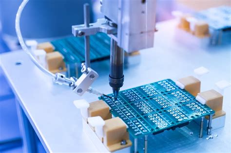
- Impedance Testing: TDR (Time Domain Reflectometry) verification.
5. Best Practices for Impedance Control
5.1 Design Guidelines
- Minimize Bends & Discontinuities: Use 45° bends instead of 90°.
- Maintain Consistent Spacing: Avoid abrupt changes in trace width.
- Use Ground Planes: Ensure uninterrupted return paths.
5.2 Material Selection
- High-Speed FR4: Suitable for most digital designs.
- Low-Loss Materials (Rogers, PTFE): Essential for RF/microwave PCBs.
5.3 Testing & Validation
- TDR Testing: Measures actual impedance post-fabrication.
- Cross-Sectional Analysis: Verifies trace dimensions.
5.4 Collaboration with Manufacturers
- Provide detailed impedance requirements in fabrication notes.
- Request impedance test reports for critical designs.
6. Common Challenges & Solution
6.1 Impedance Mismatch
- Cause: Sudden changes in trace geometry.
- Solution: Gradual tapering or impedance matching structures.
6.2 Crosstalk & EMI
- Cause: Poorly spaced differential pairs.
- Solution: Follow 3W rule (spacing ≥ 3× trace width).
6.3 Manufacturing Variability
- Cause: Process variations.
- Solution: Work with high-quality PCB vendors.
7. Future Trends in Impedance Control
- Higher Frequencies (5G, mmWave): Demanding tighter tolerances.
- Advanced Materials: Low-Dk, ultra-low-loss dielectrics.
- Automated Tuning: AI-driven impedance optimization.
Conclusion
Impedance control is a fundamental requirement in modern PCB design, ensuring reliable signal transmission in high-speed and high-frequency applications. By understanding key factors like trace geometry, dielectric properties, and manufacturing constraints, designers can achieve optimal impedance matching. Collaboration with PCB manufacturers, rigorous testing, and adherence to best practices will continue to drive advancements in this critical field.