Improving Signal Integrity of Embedded System PCBs Using Routing Techniques
Introduction
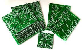
1.Printed circuit board (PCB) is the basic support for circuit components and devices in electronic products.
With the rapid development of electronic technology, embedded systems are used more and more widely. In many applications, people no longer consider function and performance, but reliability and compatibility. Printed circuit board (PCB) is the basic support for circuit components and devices in electronic products. Its design quality often directly affects the reliability and compatibility of embedded systems. In the past, the clock frequency of some low-speed circuit boards was generally only about 10 MHz. The main challenge in circuit board or package design was how to route all signal lines on a double-layer board and how to avoid damaging the package during assembly. The electrical characteristics of the interconnect are not important because the interconnect does not affect system performance. In this sense the interconnect lines in the low-speed circuit board are clear and transparent to the signals. However, with the development of embedded systems, the circuits used are basically high-frequency circuits. As the clock frequency increases, the rising edge of the signal also becomes shorter. The capacitive reactance and inductive reactance of the printed circuit to the passing signal will be far greater than The resistance of the printed circuit itself seriously affects the integrity of the signal. For embedded systems, signal integrity effects become important when clock frequencies exceed 100 MHz or rising edges are less than 1 ns.
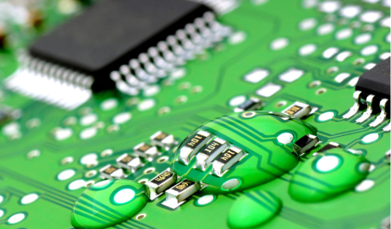
2.In PCB, signal lines are the main carrier of signal transmission
The routing of signal lines will directly determine the superiority of signal transmission, thereby directly affecting the performance of the entire system. Unreasonable wiring will seriously cause various signal integrity problems, produce timing, noise and electromagnetic interference (EMI) to the circuit, which will seriously affect the performance of the system. In this regard, this article starts from the actual electrical characteristics of signal lines in high-speed digital circuits, establishes an electrical characteristics model, finds the main reasons affecting signal integrity and methods to solve the problems, and gives the issues that should be paid attention to and the methods and techniques to be followed in wiring.
GET PCB MANUFACTURING AND ASSEMBLY QUOTE NOW!
Analysis of electrical characteristics of transmission channel
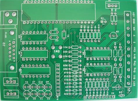
In multi-layer PCBs, most transmission lines are not only arranged on a single level, but are staggered on multiple levels, and each level is connected through vias. Therefore, in a multi-layer PCB, a typical transmission channel mainly includes three parts: transmission lines, trace corners, and vias. At low frequencies, printed lines and trace vias can be regarded as ordinary electrical connections connecting the pins of different devices, and will not have much impact on signal quality. However, in the case of high frequencies, the connectivity of printed lines, corners and vias cannot only be considered, but the influence of their electrical characteristics and parasitic parameters at high frequencies should also be considered.
1. Analysis of electrical characteristics of transmission lines in high-speed PCB
In high-speed PCB design, it is inevitable to use a large number of signal connecting lines, and the lengths vary. The delay time of the signal passing through the connecting line cannot be ignored compared with the change time of the signal itself. The signal travels on the connecting line at the speed of electromagnetic waves. Transmission, the connecting line at this time is a complex network with resistance, capacitance, and inductance, which needs to be described by a distributed parameter system model, that is, a transmission line model. A transmission line is used to transmit signals from one end to the other. It consists of 2 wires of a certain length, one is called the signal path and the other is called the return path. In low-frequency circuits, transmission lines behave as purely resistive electrical properties. In high-speed PCB, as the frequency of transmitted signals increases, the capacitive impedance between the wires decreases and the inductive impedance on the wires increases. The signal lines will no longer behave as pure resistors, that is, the signals will not only be transmitted on the wires, but also Will propagate in the medium between conductors. If the signal frequency further increases, when jωL>>R and 1/(jωC)<<R, the inductive reactance jωL and capacitive reactance 1/(jωC) on the wire become more important factors than the resistance R. Figure 1 is an equivalent model of the electrical characteristics of a transmission line.
For uniform wires, the resistance R, transmission line parasitic inductance L and parasitic capacitance C are evenly distributed (i.e. L1=L2=…=Ln; C1=C2=…=Cn+1) without considering changes in the external environment. Assume that the transmission line is a lossless transmission line, that is, when R=0, if the line parameters are: capacitance per unit length C1, inductance per unit length L1 and the total length of the transmission line is Len, then:
Total transmission line capacitance:
Total transmission line inductance:
According to the line parameters and total length of the transmission line, the characteristic impedance Z0 and time delay TD of the transmission line can be calculated. The formula is as follows:
It can be clearly seen from the above formula that increasing the capacitance and reducing the inductance can reduce the characteristic impedance; reducing the total length of the transmission line, as well as the capacitance and inductance can reduce the transmission delay on the signal line.
2. Analysis of electrical characteristics of vias in high-speed PCB
A via, usually a hole in a printed circuit board, is an important factor in multilayer PCB design. Vias can be used to securely install plug-in components or connect layer wiring. From a technological perspective, vias are generally divided into three categories: blind vias, buried vias and through holes. Blind holes are located on the top and bottom surfaces of printed circuit boards and have a certain depth. They are used to connect the surface circuits to the inner circuits below. The depth and diameter of the holes usually do not exceed a certain ratio. Buried vias refer to connection holes located on the inner layer of a printed circuit board and do not extend to the surface of the circuit board. Through holes pass through the entire circuit board and can be used to interconnect layers or serve as mounting holes for components. Because through holes are easier to implement in terms of technology and have lower costs, generally printed circuit boards use through holes instead of the other two via holes. The vias mentioned below are all considered as through holes.
The via hole is a special transmission line. In high-speed circuits, the via hole not only produces parasitic capacitance to the ground, but also has parasitic inductance. The equivalent model of its electrical characteristics is shown in Figure 2.
The main impact of the parasitic capacitance of the via on the circuit is to slow down or worsen the rising edge of the digital signal, reducing the speed of the circuit. The smaller the parasitic capacitance value of the via, the smaller the impact. If the diameter of the via isolation hole on the bottom layer is DG, the diameter of the via pad is Dv, the PCB thickness is H, and the dielectric constant of the board base material is ε, then the size of the via parasitic capacitance C is approximately:
The main impact of via parasitic inductance is to reduce the effectiveness of the power supply bypass capacitor, making the entire power supply filtering effect worse. If L is the parasitic inductance of the via, h is the length of the via, and DH is the diameter of the central drill hole, the following formula can be used to simply calculate the approximate parasitic inductance of a via:
It can be seen from the above formula that the diameter of the via hole has a small impact on the inductance, and the length of the via hole has a large impact on the inductance. In PCB, usually one end of the bypass capacitor is connected to the ground plane through a through hole, and the other end is also connected to the power plane through a through hole, so the influence of the through hole inductance will be doubled.
2.3 Contribution of transmission line corners to transmission channel signal integrity problems
When a signal propagates along a uniform line, there will be no reflection or distortion of the transmitted signal. However, corners on the transmission line will change the impedance at the transmission line, causing partial reflection and distortion of the signal. According to the capacitance per unit length of the wire C1 (unit: pF/in) and the wire width ω (unit: in), the parasitic capacitance Ccorner of each corner can be simply estimated through the following formula:
When the signal line width is narrow in a high-density circuit board, the accumulation of delays caused by the parasitic capacitance at the corners is generally unlikely to have a great impact on signal integrity. However, for high-frequency sensitive circuits, such as high-frequency clock lines, the cumulative effect caused by corner parasitic capacitance should be considered.
GET PCB AND ASSEMBLY SERVICE QUOTE NOW!
3 Use wiring techniques to suppress signal integrity problems
When a signal is output from a driving source, the currents and voltages that make up the signal treat the interconnect as an impedance network. As a signal travels along an impedance network, it constantly experiences transient impedance changes caused by interconnect lines. If the impedance felt by the signal remains the same, the signal is not distorted. Once the impedance changes, the signal is reflected at the change and distorted as it passes through the remainder of the interconnect line. If the impedance changes enough, the distortion can cause false triggering. In the signal integrity optimization design process, an important design goal is to design all interconnection lines into uniform transmission lines and reduce the length of all non-uniform transmission lines so that the impedance felt by the signals in the entire network remains unchanged. . Based on this, some methods can be summarized to use wiring techniques to suppress signal integrity problems: the routing shape of printed wires should not be tangled, branched or hard corners, try to avoid T-shaped lines and pile lines; try to keep the same network signal line Line width, reduce line width changes; reduce the length of transmission lines, increase wire width; try to increase the distance between wires; minimize vias and corners of high-speed signal lines, reduce inter-layer conversion of signal lines; rationally choose vias Size; reduce signal loop area and loop current. In summary, any feature that changes the cross-section or network geometry will change the impedance experienced by the signal. The focus of reducing signal integrity problems in wiring is to reduce impedance mutations on the transmission line so that the impedance felt by signals throughout the network remains unchanged.

GET PCB MANUFACTURING AND ASSEMBLY QUOTE NOW!
Conclusion
With the development of embedded systems, signal integrity has become an extremely important content in the PCB design of embedded systems, affecting the success or failure of the entire PCB design. When the circuit is determined, the components are selected, and the PCB layout is determined, wiring techniques can be used to suppress the occurrence of signal integrity problems, improve the reliability of the PCB, and minimize the losses caused by signal integrity problems.