Interconnection method of PCB circuit board
Electronic components and electromechanical components have electrical contacts, and the electrical connection between two discrete contacts is called interconnection. Electronic equipment must be interconnected according to the circuit schematic to achieve the predetermined function.
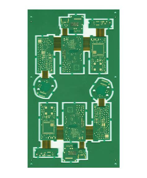
As a component of the whole machine, a printed circuit board generally cannot constitute an electronic product, and there must be problems with external connections. For example, electrical connections are required between printed circuit boards, between printed circuit boards and off-board components, and between printed circuit boards and equipment panels. Selecting the connection with the best combination of reliability, processability and economy is one of the important contents of printed circuit board design. There are many ways to connect to the outside, and they should be flexibly selected according to different characteristics.
Interconnection method of circuit board 1. Welding method
Shenzhen Benqiang Circuit (QQ800083129) said that the advantages of this connection method are simplicity, low cost, high reliability, and can avoid failures caused by poor contact; the disadvantages are that interchange and maintenance are not convenient. This method is generally suitable for situations where components have fewer external leads.
1.PCB wire welding
This method does not require any connectors. You only need to use wires to directly weld the external connection points on the PCB to the components or other parts outside the board. For example, the speaker and battery box in the radio.
When interconnecting the circuit board, you should pay attention to the following:
(1) The pads for welding wires should be as close to the edge of the PCB as possible and arranged in uniform size to facilitate welding and maintenance.
(2) In order to improve the mechanical strength of the wire connection and avoid pulling the pad or printed wire off due to the wire being pulled, holes should be drilled near the solder joints on the PCB, allowing the wires to pass through the through holes from the welding surface of the PCB, and then inserted into the pad holes from the component surface for welding.
(3) Arrange or bundle the wires neatly and fix them to the board with wire clips or other fasteners to prevent the wires from breaking due to movement.
2.PCB cable welding
The use of cable connections between two PCB printed boards is both reliable and not prone to connection errors, and the relative position of the two PCB printed boards is not restricted.
Direct welding between printed boards is often used for connections with a 90-degree angle between two printed boards. After connection, it becomes an integral PCB printed board component.
Circuit board interconnection method 2: plug-in connection method
In more complex instruments and equipment, plug-in connection method is often used. This “building block” structure not only ensures the quality of mass production of products, reduces the cost of the system, but also provides convenience for debugging and maintenance. When the equipment fails, the maintenance personnel do not have to check the component level (that is, check the cause of the failure and trace it back to the specific components. This work takes a lot of time). As long as it is determined which board is abnormal, it can be replaced immediately, troubleshooting can be done in the shortest time, shortening downtime and improving equipment utilization. The replaced circuit board can be repaired in ample time and used as a spare part after repair.
- Printed board socket Shenzhen Benqiang Circuit (tel: 075529606089) pointed out that this connection method is often used in more complex instruments and equipment. This method is to make a printed plug from the edge of the PCB printed board. The plug part is designed according to the size of the socket, the number of contacts, the distance between contacts, the position of the positioning holes, etc., so that it matches the dedicated PCB printed board socket.
When making the board, the plug part needs to be gold-plated to improve wear resistance and reduce contact resistance. This method is simple to assemble, has good interchangeability and maintenance performance, and is suitable for standardized mass production. Its disadvantages are that the cost of the printed board is increased, and the manufacturing precision and process requirements of the printed board are high; the reliability is slightly poor, and the contact is often poor due to oxidation of the plug part or aging of the socket reed. In order to improve the reliability of external connection, the same lead wire is often connected in parallel through the contacts on the same side or both sides of the circuit board.
The PCB printed board socket connection method is often used for products with multi-board structures. The socket and the printed board or bottom board are of two types: reed type and pin type.
- Standard pin connection
This method can be used for external connection of printed boards, especially in small instruments. Pin connection is often used. The two printed circuit boards are connected through standard pins. The two printed circuit boards are generally parallel or vertical, which makes mass production easy.


