Inverter Board Assembly: A Comprehensive Guide
Introduction
Inverter boards are critical components in a wide range of electronic devices, from household appliances to industrial machinery. They play a pivotal role in converting direct current (DC) to alternating current (AC), enabling the operation of devices that rely on AC power. The assembly of inverter boards is a complex process that requires precision, expertise, and adherence to strict quality standards. This article delves into the intricacies of inverter board assembly, covering the key components, assembly processes, challenges, and best practices.
Key Components of an Inverter Board
Before diving into the assembly process, it is essential to understand the key components that make up an inverter board. These components work together to ensure the efficient conversion of DC to AC power.
- Microcontroller Unit (MCU): The MCU is the brain of the inverter board. It controls the overall operation of the inverter, including the switching of transistors, monitoring of input and output voltages, and protection mechanisms.
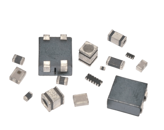
- Power Transistors (MOSFETs/IGBTs): Power transistors, such as MOSFETs (Metal-Oxide-Semiconductor Field-Effect Transistors) or IGBTs (Insulated Gate Bipolar Transistors), are responsible for switching the DC input to generate the AC output. These components are crucial for the efficiency and reliability of the inverter.
- Capacitors: Capacitors are used to store and release electrical energy, smoothing out voltage fluctuations and ensuring a stable output. They are available in various types, including electrolytic, ceramic, and film capacitors, each with specific applications.
- Inductors: Inductors are used in conjunction with capacitors to form LC (inductor-capacitor) filters, which help in reducing noise and harmonics in the output waveform.
- Diodes: Diodes are used for rectification, allowing current to flow in one direction only. They are essential for converting AC to DC in some inverter designs and for protecting the circuit from reverse voltage.
- Resistors: Resistors are used to control the flow of current and voltage levels within the circuit. They are crucial for setting the operating parameters of the inverter.
- Transformers: In some inverter designs, transformers are used to step up or step down the voltage levels. They provide electrical isolation between the input and output, enhancing safety.
- Heat Sinks: Heat sinks are used to dissipate heat generated by power transistors and other components. Proper thermal management is essential to ensure the longevity and reliability of the inverter board.
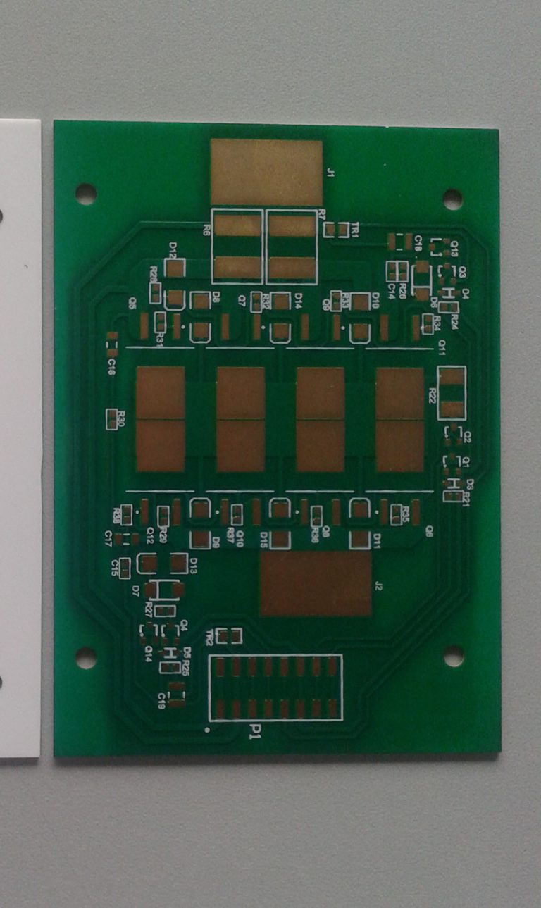
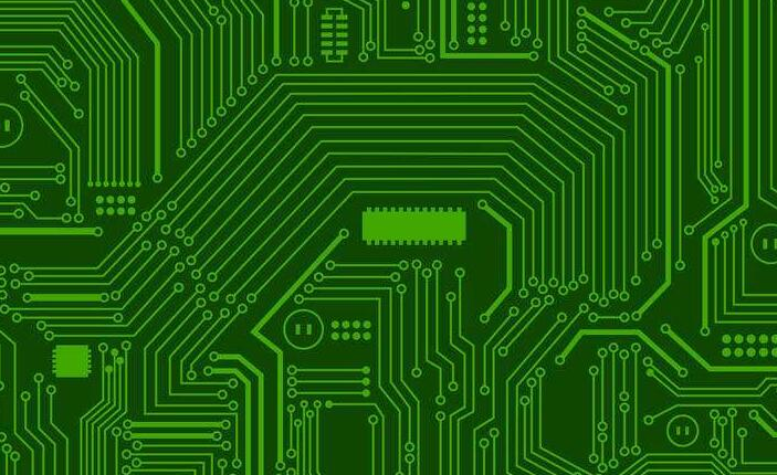
- Printed Circuit Board (PCB): The PCB serves as the foundation for mounting and interconnecting all the components. It provides the necessary electrical connections and mechanical support.
Inverter Board Assembly Process
The assembly of an inverter board involves several stages, each requiring careful attention to detail. The process can be broadly divided into the following steps:
- Design and Layout: The first step in inverter board assembly is the design and layout of the PCB. This involves creating a schematic diagram that outlines the electrical connections between components. The layout must consider factors such as component placement, trace routing, and thermal management. Advanced software tools, such as Altium Designer or Eagle, are used to create the PCB design.
- Component Procurement: Once the design is finalized, the next step is to procure the necessary components. It is crucial to source high-quality components from reputable suppliers to ensure the reliability and performance of the inverter board. Components should be selected based on their specifications, including voltage ratings, current ratings, and temperature tolerances.
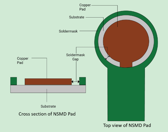
- PCB Fabrication: The PCB fabrication process involves creating the physical board based on the design. This includes etching the copper traces, drilling holes for component leads, and applying solder mask and silkscreen. The fabrication process must adhere to strict quality standards to ensure the integrity of the PCB.
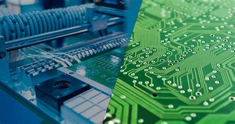
- Component Placement: The next step is the placement of components on the PCB. This can be done manually for small-scale production or using automated pick-and-place machines for larger volumes. The placement process must be precise to ensure proper alignment and soldering of components.
- Soldering: Soldering is the process of attaching components to the PCB using solder, a metal alloy that melts at a relatively low temperature. There are two primary soldering methods used in inverter board assembly:
- Wave Soldering: In wave soldering, the PCB is passed over a wave of molten solder, which attaches the components to the board. This method is typically used for through-hole components.
- Reflow Soldering: Reflow soldering involves applying solder paste to the PCB, placing the components, and then heating the board in a reflow oven to melt the solder. This method is commonly used for surface-mount components.
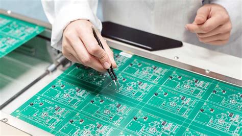
- Inspection and Testing: After soldering, the assembled inverter board undergoes inspection and testing to ensure quality and functionality. Visual inspection is performed to check for soldering defects, such as bridges, voids, or misaligned components. Automated optical inspection (AOI) systems may also be used for more detailed analysis. Functional testing involves powering up the board and verifying that it operates as intended, including checking the output waveform, voltage levels, and efficiency.
- Conformal Coating: To protect the inverter board from environmental factors such as moisture, dust, and temperature fluctuations, a conformal coating may be applied. This thin layer of protective material helps to extend the lifespan of the board and improve its reliability.
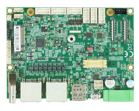
- Final Assembly: In some cases, the inverter board may be integrated into a larger assembly, such as an inverter module or an electronic device. This may involve mounting the board in a housing, connecting it to other components, and securing it with screws or other fasteners.
Challenges in Inverter Board Assembly
The assembly of inverter boards presents several challenges that must be addressed to ensure the production of high-quality, reliable products.
- Thermal Management: Inverter boards generate significant heat, particularly from power transistors. Effective thermal management is essential to prevent overheating, which can lead to component failure or reduced lifespan. This involves the use of heat sinks, thermal pads, and proper component placement to facilitate heat dissipation.
- Component Sourcing: The availability and quality of components can significantly impact the assembly process. Supply chain disruptions, counterfeit components, and variations in component specifications can pose challenges. It is essential to work with reputable suppliers and conduct thorough quality checks.
- Soldering Defects: Soldering is a critical step in the assembly process, and defects such as cold joints, solder bridges, or insufficient solder can lead to poor electrical connections and board failure. Proper soldering techniques, equipment calibration, and inspection are necessary to minimize defects.
- Electromagnetic Interference (EMI): Inverter boards can generate electromagnetic interference, which can affect the performance of nearby electronic devices. Proper PCB layout, shielding, and filtering are necessary to mitigate EMI and ensure compliance with regulatory standards.
- Testing and Quality Assurance: Ensuring the functionality and reliability of inverter boards requires comprehensive testing and quality assurance processes. This includes functional testing, environmental testing, and stress testing to identify and address potential issues.
Best Practices for Inverter Board Assembly
To overcome the challenges and ensure the successful assembly of inverter boards, several best practices should be followed:
- Design for Manufacturability (DFM): The PCB design should be optimized for manufacturability, considering factors such as component placement, trace routing, and thermal management. DFM guidelines help to minimize assembly issues and improve yield rates.
- Use of High-Quality Components: Sourcing high-quality components from reputable suppliers is essential for the reliability and performance of the inverter board. Components should be selected based on their specifications and suitability for the application.
- Automated Assembly: For large-scale production, automated assembly processes, such as pick-and-place machines and reflow soldering, can improve efficiency and consistency. Automation reduces the risk of human error and increases throughput.
- Rigorous Testing: Comprehensive testing is essential to ensure the functionality and reliability of the inverter board. This includes functional testing, environmental testing, and stress testing to identify and address potential issues.
- Continuous Improvement: The assembly process should be continuously monitored and improved based on feedback and data analysis. This includes identifying and addressing root causes of defects, optimizing processes, and implementing best practices.
Conclusion
The assembly of inverter boards is a complex and critical process that requires precision, expertise, and adherence to strict quality standards. By understanding the key components, following best practices, and addressing the challenges, manufacturers can produce high-quality inverter boards that meet the demands of modern electronic devices. As technology continues to advance, the importance of efficient and reliable inverter board assembly will only grow, driving innovation and excellence in the field.