Ipc standards for pcb assembly
Understanding IPC-A-610: The Essential Standard for PCB Assembly Quality
In the realm of electronics manufacturing, ensuring the quality and reliability of printed circuit board (PCB) assemblies is paramount. One of the most widely recognized standards that guide this process is the IPC-A-610, which serves as a critical benchmark for assessing the acceptability of electronic assemblies. This standard, developed by the Institute for Printed Circuits (IPC), provides comprehensive criteria for the workmanship of electronic assemblies, thereby playing a crucial role in maintaining high-quality standards across the industry.
To begin with, IPC-A-610 is an essential document that outlines the acceptability criteria for various aspects of PCB assembly, including soldering, component placement, and mechanical assembly.
It is widely used by manufacturers, assemblers, and quality control professionals to ensure that products meet the necessary quality requirements. The standard is applicable to a wide range of industries, from consumer electronics to aerospace, and is instrumental in minimizing defects and enhancing the reliability of electronic products.
One of the key features of IPC-A-610 is its classification system, which categorizes products into three classes based on their intended use and reliability requirements.
Class 1 is designated for general electronic products, where the primary concern is the function of the completed assembly. Class 2 is for dedicated service electronic products, where continued performance and extended life are required, but uninterrupted service is not critical. Class 3 is reserved for high-performance electronic products, where continued high performance or performance-on-demand is critical, and equipment downtime cannot be tolerated. This classification system allows manufacturers to tailor their quality control processes to meet the specific needs of their products.
Moreover, IPC-A-610 provides detailed visual illustrations and descriptions of acceptable and non-acceptable conditions for various assembly processes.
This includes criteria for solder joints, component placement, and the presence of foreign materials, among others. By offering clear and concise guidelines, the standard helps to eliminate ambiguity and ensures that all parties involved in the manufacturing process have a common understanding of quality expectations. This is particularly important in a globalized industry where manufacturers and suppliers may be located in different parts of the world.
In addition to its role in quality assurance, IPC-A-610 also serves as a valuable training tool for assembly line workers and quality inspectors.
By familiarizing themselves with the standard, personnel can develop a keen eye for identifying defects and understanding the nuances of high-quality assembly work. This not only improves the overall quality of the products but also enhances the efficiency of the manufacturing process by reducing the need for rework and repairs.
Furthermore, adherence to IPC-A-610 can have significant implications for a company’s reputation and competitiveness in the market.
Products that consistently meet or exceed the standards set forth in IPC-A-610 are more likely to gain the trust of customers and stakeholders, leading to increased business opportunities and market share. Conversely, failure to comply with these standards can result in costly recalls, damage to brand reputation, and potential legal liabilities.
In conclusion, IPC-A-610 is an indispensable standard for ensuring the quality and reliability of PCB assemblies. Its comprehensive criteria, classification system, and visual guidelines provide a robust framework for manufacturers to achieve excellence in electronic assembly. By adhering to this standard, companies can not only enhance their product quality but also strengthen their position in the competitive electronics market.
IPC J-STD-001: Best Practices for Soldering in PCB Assembly
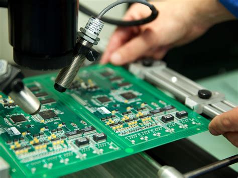
IPC J-STD-001 is a critical standard in the realm of printed circuit board (PCB) assembly, providing comprehensive guidelines for soldering processes. This standard is widely recognized and adopted across the electronics manufacturing industry, ensuring that soldering practices meet high-quality benchmarks. As the demand for reliable electronic devices continues to grow, adherence to IPC J-STD-001 becomes increasingly important for manufacturers aiming to produce durable and efficient products.
To begin with, IPC J-STD-001 outlines the materials, methods, and verification criteria necessary for producing high-quality soldered interconnections
. It emphasizes the importance of selecting appropriate soldering materials, such as solder alloys and fluxes, which are crucial for achieving optimal solder joints. The standard specifies the characteristics of these materials, ensuring they are compatible with the components and substrates used in PCB assembly. By adhering to these guidelines, manufacturers can prevent common issues such as poor wetting, voids, and insufficient solder coverage, which can compromise the functionality of the final product.
Moreover, IPC J-STD-001 provides detailed instructions on the soldering process itself, covering various techniques such as hand soldering, wave soldering, and reflow soldering.
Each method has its own set of parameters and best practices, which are meticulously detailed in the standard. For instance, in reflow soldering, the standard highlights the importance of controlling the temperature profile to prevent thermal damage to components and substrates. By following these guidelines, manufacturers can ensure that solder joints are formed correctly, with adequate mechanical strength and electrical conductivity.
In addition to the technical aspects of soldering, IPC J-STD-001 also addresses the human factor in the assembly process.
It underscores the necessity of training and certifying personnel involved in soldering operations. Skilled operators are essential for maintaining the quality and consistency of soldered connections, as they can identify and rectify potential issues during the assembly process. The standard provides a framework for training programs, ensuring that personnel are well-versed in the latest soldering techniques and quality control measures.
Furthermore, IPC J-STD-001 emphasizes the importance of inspection and testing in verifying the quality of soldered connections.
It outlines various inspection methods, including visual inspection and automated optical inspection (AOI), to detect defects such as solder bridges, insufficient solder, and misaligned components. The standard also recommends electrical testing to ensure the functionality of the assembled PCB. By incorporating these inspection and testing procedures, manufacturers can identify and address defects early in the production process, reducing the risk of failures in the field.
Transitioning to the broader implications, adherence to IPC J-STD-001 not only enhances the quality of individual solder joints but also contributes to the overall reliability and performance of electronic devices.
As electronic products become more complex and miniaturized, the margin for error in PCB assembly diminishes. Therefore, following the best practices outlined in IPC J-STD-001 is essential for manufacturers striving to meet the stringent demands of modern electronics.
In conclusion, IPC J-STD-001 serves as a vital resource for ensuring high-quality soldering in PCB assembly. By providing detailed guidelines on materials, processes, personnel training, and inspection, the standard helps manufacturers produce reliable and efficient electronic devices. As the electronics industry continues to evolve, adherence to IPC J-STD-001 will remain a cornerstone of quality assurance in PCB assembly, fostering innovation and excellence in electronic manufacturing.
The Role of IPC-7711/7721 in PCB Assembly Rework and Repair
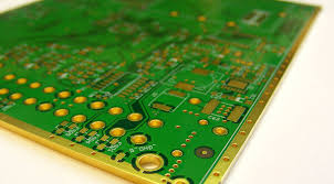
In the realm of printed circuit board (PCB) assembly, maintaining high standards of quality and reliability is paramount. The IPC-7711/7721 standards play a crucial role in ensuring that rework and repair processes meet these stringent requirements. These standards, developed by the Institute for Printed Circuits (IPC), provide comprehensive guidelines for the rework, modification, and repair of electronic assemblies, thereby ensuring that the integrity and functionality of PCBs are preserved even after undergoing such processes.
To begin with, IPC-7711/7721 standards are essential for maintaining consistency and quality in PCB assembly rework and repair.
They offer detailed procedures and methodologies that technicians can follow to address defects or make necessary modifications. This is particularly important in industries where PCBs are integral to the operation of complex electronic systems, such as aerospace, automotive, and telecommunications. By adhering to these standards, manufacturers can ensure that any rework or repair does not compromise the performance or reliability of the final product.
Moreover, the IPC-7711/7721 standards are designed to be comprehensive, covering a wide range of rework and repair scenarios.
They include guidelines for handling various types of components, from through-hole to surface-mount devices, and provide instructions for dealing with different types of defects, such as soldering issues, component damage, and trace repairs. This breadth of coverage ensures that technicians have access to the necessary information to address almost any issue that may arise during the PCB assembly process.
In addition to providing technical guidance, the IPC-7711/7721 standards also emphasize the importance of proper training and certification for technicians involved in rework and repair.
By ensuring that personnel are adequately trained and certified, manufacturers can reduce the risk of errors and improve the overall quality of their products. This focus on training is crucial, as the complexity of modern PCBs requires a high level of skill and expertise to perform rework and repair tasks effectively.
Furthermore, the adoption of IPC-7711/7721 standards can lead to significant cost savings for manufacturers.
By providing clear and effective procedures for rework and repair, these standards help to minimize the need for scrapping defective boards, which can be a costly endeavor. Instead, manufacturers can salvage and restore PCBs to their original functionality, thereby reducing waste and improving the overall efficiency of the production process.
Another important aspect of the IPC-7711/7721 standards is their role in facilitating communication and collaboration between different stakeholders in the PCB assembly process.
By providing a common framework and language for rework and repair, these standards help to ensure that all parties involved, from designers to technicians to quality assurance personnel, are on the same page. This alignment is crucial for maintaining the quality and reliability of PCBs, as it helps to prevent misunderstandings and miscommunications that could lead to defects or failures.
In conclusion, the IPC-7711/7721 standards are indispensable tools for ensuring the quality and reliability of PCB assembly rework and repair. By providing comprehensive guidelines, emphasizing the importance of training, and facilitating communication, these standards help manufacturers maintain high standards of quality while also achieving cost savings and efficiency improvements. As the complexity of electronic assemblies continues to grow, the role of IPC-7711/7721 in guiding rework and repair processes will only become more critical, underscoring their importance in the ever-evolving landscape of PCB assembly.
How IPC-2221 Influences PCB Design for Reliable Assembly
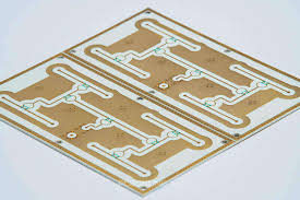
The IPC-2221 standard plays a pivotal role in the design and assembly of printed circuit boards (PCBs), serving as a cornerstone for ensuring reliability and functionality in electronic devices. As the foundation for PCB design, IPC-2221 provides comprehensive guidelines that influence various aspects of the design process, ultimately impacting the assembly and performance of the final product. By adhering to these standards, designers and manufacturers can achieve a balance between innovation and reliability, which is crucial in today’s rapidly evolving technological landscape.
To begin with, IPC-2221 sets forth general design requirements that encompass a wide range of considerations, from material selection to layout specifications.
These guidelines are essential for creating PCBs that can withstand the rigors of manufacturing and operational environments. For instance, the standard outlines criteria for selecting materials that offer the necessary thermal and mechanical properties, ensuring that the PCB can endure the stresses of assembly processes such as soldering and reflow. By specifying these requirements, IPC-2221 helps designers make informed decisions that enhance the durability and longevity of the PCB.
Moreover, IPC-2221 addresses the importance of trace routing and spacing, which are critical factors in preventing electrical failures and ensuring signal integrity.
The standard provides detailed recommendations on the minimum spacing between conductive elements, which is vital for avoiding short circuits and crosstalk. By following these guidelines, designers can optimize the layout of the PCB to minimize electromagnetic interference and improve overall performance. This attention to detail is particularly important in high-density designs, where the risk of signal degradation is heightened.
In addition to layout considerations, IPC-2221 also emphasizes the significance of thermal management in PCB design.
Effective thermal management is crucial for maintaining the reliability of electronic components, as excessive heat can lead to premature failure. The standard offers guidance on designing PCBs with adequate thermal pathways, such as the use of thermal vias and heat sinks, to dissipate heat efficiently. By incorporating these features into the design, manufacturers can enhance the thermal performance of the PCB, thereby extending the lifespan of the device.
Furthermore, IPC-2221 influences the assembly process by providing guidelines for component placement and mounting.
Proper component placement is essential for achieving reliable solder joints and minimizing the risk of defects during assembly. The standard outlines best practices for positioning components to facilitate efficient soldering and inspection, which are critical for ensuring the quality of the final product. By adhering to these recommendations, manufacturers can reduce the likelihood of assembly-related issues, such as misalignment and insufficient solder coverage.
In conclusion, IPC-2221 serves as a fundamental framework for PCB design, guiding designers and manufacturers in creating reliable and high-performance electronic devices. By addressing key aspects such as material selection, trace routing, thermal management, and component placement, the standard ensures that PCBs are designed with reliability and manufacturability in mind. As technology continues to advance, the importance of adhering to IPC-2221 cannot be overstated, as it provides the necessary foundation for achieving excellence in PCB design and assembly. Through its comprehensive guidelines, IPC-2221 not only influences the design process but also plays a crucial role in shaping the future of electronic manufacturing.


