Is there a difference between gold and silver plating on PCBs?
Today, we’ll share some basic PCB knowledge. For example, do different PCB colors affect their performance? What are the differences between gold and silver plating? The following sections will explain each of these.
Which is more noble? Unveiling the mysteries of PCB colors
Many DIY enthusiasts will find the dazzling array of PCB colors used in various motherboards and graphics cards on the market. Common PCB colors include black, green, blue, yellow, purple, red, and brown. Some manufacturers have also creatively developed PCBs in colors like white and pink.
Traditionally, black PCBs seem to represent high-end products, while red, yellow, and other colors are reserved for low-end products. Is this true?
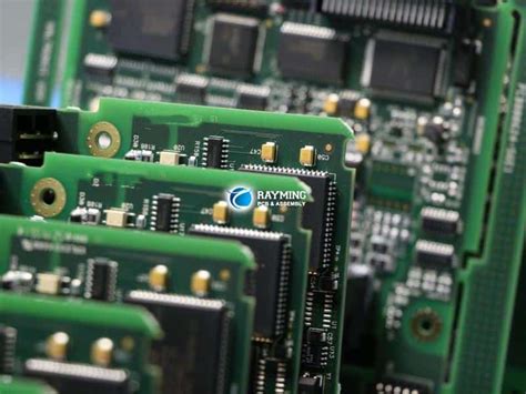
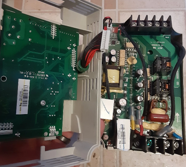
The copper layer of a PCB without solder mask is easily oxidized when exposed to air.
We know that copper is present on both sides of a PCB. Whether the copper layer is produced using additive or subtractive methods, the final result is a smooth, unprotected surface. Although copper isn’t as chemically active as aluminum, iron, or magnesium, pure copper is highly susceptible to oxidation when exposed to oxygen in the presence of water. Because air contains oxygen and water vapor, the surface of pure copper quickly undergoes oxidation upon contact with air. Because the copper layer in a PCB is very thin, oxidized copper becomes a poor conductor of electricity, significantly impairing the overall electrical performance of the PCB.
To prevent copper oxidation, separate the soldered and non-soldered areas of the PCB during soldering, and protect the PCB surface, engineers have developed a special coating. This coating can be easily applied to the PCB surface, forming a thick protective layer that blocks contact between the copper and air. This coating is called solder mask, and the material used is solder mask lacquer.
Since it’s called lacquer, it comes in different colors. While original solder mask can be colorless and transparent, PCBs often require fine text printing for ease of repair and manufacturing. Transparent solder mask only reveals the base color of the PCB, making it less appealing for manufacturing, repair, and sales. Therefore, engineers added various colors to solder mask, ultimately resulting in black, red, or blue PCBs.
2.Black PCBs make it difficult to see traces, making repairs difficult.
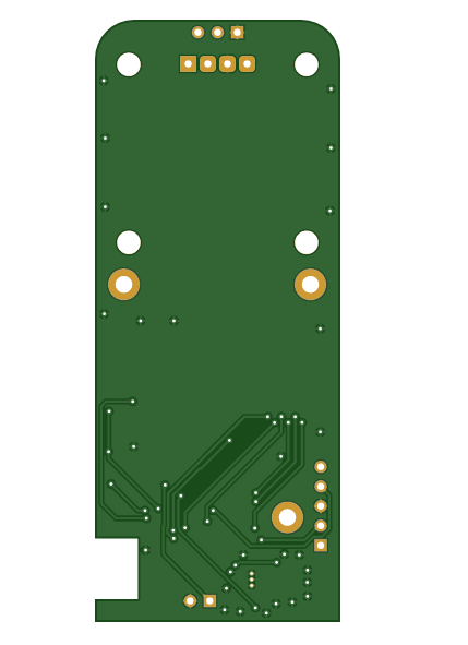
From this point of view, PCB color has nothing to do with PCB quality. The difference between black PCBs and other colors, such as blue or yellow, lies in the color of the solder mask applied at the end. If the PCB design and manufacturing process are identical, color has no impact on performance or heat dissipation.
As for black PCBs, since they almost completely cover the surface traces, they pose significant challenges for later repairs, making them less convenient to manufacture and use. Consequently, in recent years, people have gradually shifted away from black solder mask and toward dark green, dark brown, dark blue, and other colors to facilitate manufacturing and repair.
At this point, the issue of PCB color is largely clear. The notion that “color represents high-end or low-end” arises because manufacturers favor black PCBs for high-end products and red, blue, green, and yellow for low-end products. To sum it up: the product confers meaning on color, not the other way around.
3.What are the benefits of using precious metals like gold and silver on PCBs?
Now that we’ve explained color, let’s talk about the precious metals used on PCBs! Some manufacturers specifically mention using special processes like gold and silver plating when promoting their products. So, what exactly is the purpose of these processes?
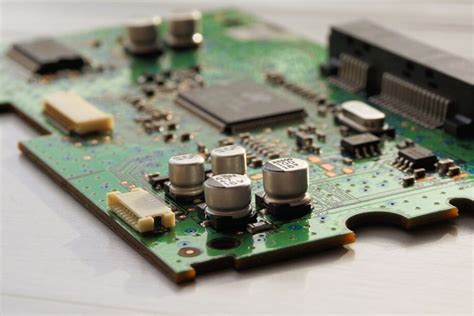
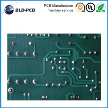
To solder components onto a PCB surface, a portion of the copper layer must be exposed for soldering. This exposed copper layer is called a pad. Pads are typically rectangular or circular and very small. As we learned above, the copper used in PCBs is highly susceptible to oxidation. Therefore, after applying solder mask, the only copper exposed to air is the pad.
Oxidized copper on the pad not only makes soldering difficult, but also significantly increases resistivity, seriously affecting the performance of the final product. Therefore, engineers have devised various methods to protect the pads. These include plating with inert gold, chemically coating the surface with a layer of silver, or coating the copper layer with a special chemical film to prevent the pad from coming into contact with air.
The exposed pads on a PCB have the copper layer directly exposed. This area needs protection to prevent oxidation.
From this perspective, whether it’s gold or silver, the purpose of the process itself is to prevent oxidation and protect the pads, thereby ensuring good product quality during the subsequent soldering process.
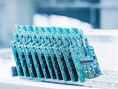
However, the use of different metals imposes requirements on the storage time and conditions of the PCBs used by the production factory. Therefore, PCB factories generally use vacuum packaging machines to package the PCBs after production and before delivery to customers to minimize oxidation damage.
Before the components are soldered on the machine, the board manufacturer also tests the PCBs for oxidation and removes oxidized PCBs to ensure good product quality. The boards that consumers receive have undergone various tests. Even after long-term use, oxidation will mostly occur at the plug-in connectors and has little impact on the pads and already soldered components.
Since silver and gold have lower electrical resistance, will the use of special metals such as silver and gold reduce the heat generated by the PCB during use?
As we know, the biggest factor affecting heat generation is resistance. Resistance is related to the conductor’s material, cross-sectional area, and length. The metal thickness on the pad surface can be as little as 0.01 mm. If the pad is treated with OST (organic overcoat), there’s no excess thickness at all. Such a tiny thickness results in a resistance that’s practically zero, even incalculable, and certainly doesn’t affect heat generation.
PCBs are typically rectangular or circular, with a very small area. As we’ve seen above, the copper used in PCBs is highly susceptible to oxidation. Therefore, after solder mask is applied, the only copper exposed to air is the pad itself.
Oxidized copper on the pad not only makes soldering difficult, but also significantly increases resistivity, severely impacting the performance of the final product. Consequently, engineers have devised various methods to protect the pads. These include plating with inert gold, chemically coating the surface with silver, or coating the copper with a special chemical film to prevent contact between the pad and air.