Key Considerations When Designing Microcontroller Peripheral Circuits
Introduction
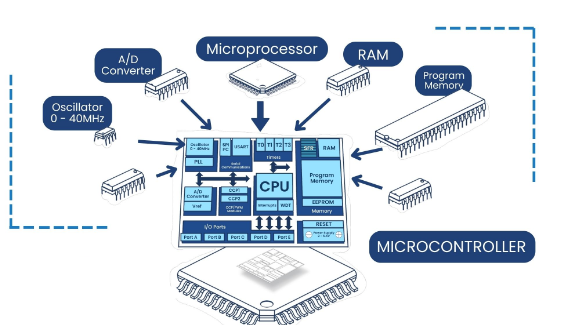
Designing peripheral circuits for microcontrollers (MCUs) is a critical aspect of embedded system development. The performance, reliability, and efficiency of an MCU-based system heavily depend on how well its peripheral circuits are designed. Peripheral circuits include power supply, clock generation, reset circuits, input/output (I/O) interfaces, communication modules (UART, SPI, I2C), analog-to-digital converters (ADCs), and sensor interfaces. Poorly designed peripheral circuits can lead to system instability, noise interference, signal integrity issues, and even hardware failure.
This article explores the key considerations when designing microcontroller peripheral circuits, covering power supply design, signal integrity, noise reduction, communication interfaces, and protection mechanisms.
1. Power Supply Design
1.1 Voltage Regulation and Decoupling
Microcontrollers require a stable and clean power supply for proper operation. Key considerations include:
- Voltage Levels: Ensure the power supply matches the MCU’s operating voltage (e.g., 3.3V, 5V, or lower for low-power devices).
- Linear vs. Switching Regulators:
- Linear regulators (e.g., LM1117) provide low noise but are less efficient.
- Switching regulators (e.g., Buck converters) are more efficient but may introduce noise.
- Decoupling Capacitors: Place decoupling capacitors (typically 0.1µF ceramic) near the MCU’s power pins to filter high-frequency noise. Larger capacitors (e.g., 10µF electrolytic) help stabilize voltage during transient loads.
1.2 Power Sequencing
Some MCUs and peripherals require specific power-up sequences to avoid latch-up or improper initialization. Check the datasheet for:
- Core voltage (Vcore) vs. I/O voltage (VDD) requirements.
- Power-on reset (POR) thresholds.
1.3 Low-Power Considerations
For battery-operated devices:
- Use low-dropout regulators (LDOs).
- Implement sleep modes and dynamic power gating.
- Minimize leakage currents in unused peripherals.
2. Clock Circuit Design
2.1 Crystal Oscillators vs. RC Oscillators
- Crystal Oscillators: Provide high accuracy (essential for UART, USB, and precise timing). Requires load capacitors (e.g., 22pF) and proper PCB layout.
- RC Oscillators: Cheaper but less stable; suitable for non-critical timing applications.
2.2 PCB Layout for Clock Signals
- Keep clock traces short and away from high-noise signals.
- Avoid sharp bends to prevent impedance mismatches.
- Use ground planes to reduce electromagnetic interference (EMI).
3. Reset Circuit Design
A reliable reset circuit ensures the MCU starts correctly. Options include:
- Manual Reset Button: With a debounce circuit (RC filter).
- Power-On Reset (POR) Circuit: Uses an RC delay or a dedicated reset IC (e.g., MAX809).
- Brown-Out Detection (BOD): Some MCUs have built-in BOD; otherwise, use an external supervisor IC.
4. Signal Integrity and Noise Reduction
4.1 Proper Grounding
- Use a star grounding topology to avoid ground loops.
- Separate analog and digital grounds, connecting them at a single point.
4.2 Shielding and Filtering
- Use ferrite beads for high-frequency noise suppression.
- Add series resistors (e.g., 22Ω–100Ω) to dampen signal reflections.
4.3 Avoiding Crosstalk
- Keep high-speed signals (e.g., SPI, USB) away from analog inputs.
- Use differential signaling (e.g., RS485, CAN) for long-distance communication.
5. Communication Interfaces
5.1 UART/RS232/RS485
- Level Shifting: Use ICs like MAX232 for RS232 or SN65HVD72 for RS485.
- Termination Resistors: Required for RS485 (typically 120Ω).
5.2 I2C and SPI
- Pull-Up Resistors: I2C requires pull-ups (typically 4.7kΩ).
- Signal Integrity: Keep SPI traces short for high-speed operation.
5.3 USB and Ethernet
- Impedance matching (90Ω differential for USB).
- Use EMI filters and ESD protection diodes.
6. Analog Circuit Design
6.1 ADC Considerations
- Use a stable reference voltage (VREF).
- Add low-pass filters to reduce noise.
- Ensure proper sampling time and avoid signal aliasing.
6.2 Sensor Interfaces
- For thermistors, RTDs, and strain gauges, use precision amplifiers and noise filtering.
- For capacitive sensors, consider guard rings to reduce stray capacitance.
7. Protection Circuits
7.1 Overvoltage and ESD Protection
- TVS diodes for ESD protection (e.g., USB, GPIO).
- Schottky diodes for overvoltage clamping.
7.2 Reverse Polarity Protection
- Use a series diode or MOSFET-based protection circuit.
7.3 Current Limiting
- Place polyfuses or current-limiting ICs to prevent damage from shorts.
8. PCB Layout Best Practices
- Component Placement: Group related components (e.g., place decoupling caps near MCU).
- Trace Routing:
- Avoid 90-degree bends.
- Use wider traces for high-current paths.
- Thermal Management: Ensure proper heat dissipation for power components.
9. Testing and Debugging
- Use oscilloscopes to check signal integrity.
- Verify power supply ripple and noise levels.
- Test communication interfaces with logic analyzers.
Conclusion
Designing robust microcontroller peripheral circuits requires careful attention to power supply stability, signal integrity, noise reduction, and protection mechanisms. By following best practices in PCB layout, grounding, and component selection, engineers can ensure reliable and efficient embedded systems. Always refer to the MCU’s datasheet and application notes for specific design guidelines.
By addressing these considerations, designers can minimize debugging efforts and improve the overall performance of their microcontroller-based systems.