Manual PCB Assembly: A Comprehensive Guide
Introduction
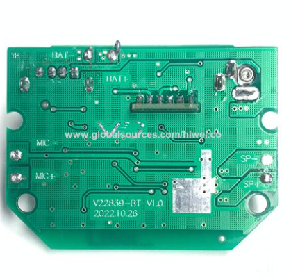
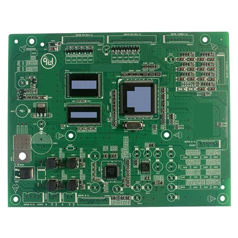
Printed Circuit Boards (PCBs) are the backbone of modern electronics, providing the necessary connections for components to function together. While automated assembly processes dominate mass production, manual PCB assembly remains essential for prototyping, low-volume production, and specialized applications. This guide explores the techniques, tools, challenges, and best practices of manual PCB assembly.
Understanding Manual PCB Assembly
Manual PCB assembly involves hand-placing and soldering components onto a PCB without the use of automated machinery. This method is preferred when:
- Prototyping – Engineers and hobbyists manually assemble boards to test designs before mass production.
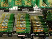
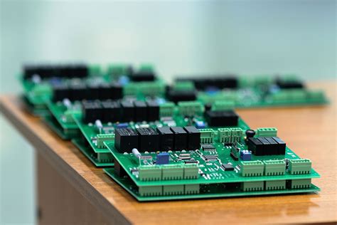
- Low-Volume Production – Small batches may not justify the cost of automated assembly.
- Repair and Rework – Damaged or incorrectly assembled boards often require manual intervention.
- Specialized Components – Some parts (e.g., large connectors, heat-sensitive components) are better handled manually.
Tools and Equipment for Manual PCB Assembly
Successful manual assembly requires the right tools:
1. Soldering Tools
- Soldering Iron – A temperature-controlled iron (30W-60W) with a fine tip is ideal for precision work.
- Solder Wire – Lead-based (Sn60/Pb40) or lead-free (SAC305) solder with flux core.
- Soldering Station – Advanced stations offer adjustable temperature and ESD protection.
2. Handling Tools
- Tweezers – Fine-tip tweezers help place small surface-mount (SMD) components.
- Magnifying Glass/Microscope – Essential for inspecting small solder joints.
- Helping Hands – A stand with clips holds PCBs steady during soldering.
3. Cleaning and Inspection Tools
- Flux Remover/Isopropyl Alcohol – Cleans residual flux after soldering.
- Multimeter/Oscilloscope – Tests electrical connections.
- Microscope or Magnifying Lamp – Inspects solder joints for defects.
4. Desoldering Tools
- Solder Wick (Braided Copper) – Removes excess solder.
- Desoldering Pump (Solder Sucker) – Extracts molten solder from joints.
Step-by-Step Manual PCB Assembly Process
Step 1: Preparing the PCB and Components
- Organize Components – Sort them by type (resistors, capacitors, ICs) to avoid confusion.
- Check PCB Layout – Verify footprints match component sizes.
- Clean the PCB – Remove dust or oxidation for better solder adhesion.
Step 2: Placing Components
- Through-Hole Components (THT) – Insert leads into holes and bend slightly to hold them in place.
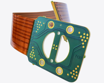
- Surface-Mount Components (SMD) – Use tweezers to position them accurately on pads.
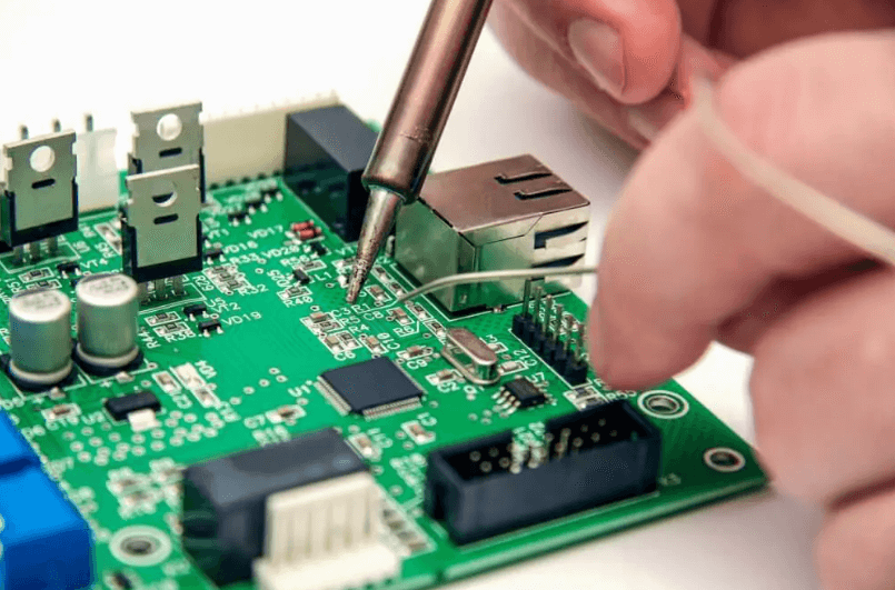
Step 3: Soldering
- Through-Hole Soldering
- Heat the pad and component lead with the soldering iron.
- Apply solder until it flows smoothly around the joint (avoid cold solder joints).
- Trim excess leads with flush cutters.
- Surface-Mount Soldering
- Apply a small amount of solder to one pad.
- Position the component and reheat the solder to secure it.
- Solder remaining pins carefully (drag soldering for multi-pin components).
Step 4: Inspection and Testing
- Visual Inspection – Check for bridges, insufficient solder, or misaligned parts.
- Continuity Test – Use a multimeter to verify connections.
- Functional Test – Power up the board to ensure proper operation.
Step 5: Cleaning and Finishing
- Remove flux residues with isopropyl alcohol.
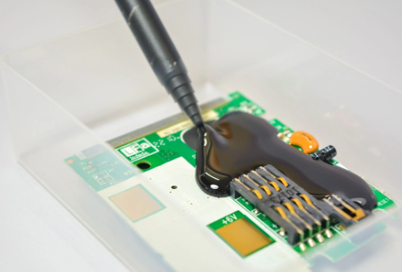
- Apply conformal coating if required for protection.
Common Challenges in Manual PCB Assembly
- Component Misalignment – Small SMD parts can shift during soldering.
- Solution: Use a small amount of adhesive or rework with a soldering iron.
- Solder Bridges – Accidental connections between pins.
- Solution: Use solder wick or a desoldering pump to remove excess solder.
- Cold Solder Joints – Poor connections due to insufficient heat.
- Solution: Reheat the joint and add flux if necessary.
- ESD Damage – Static electricity can destroy sensitive components.
- Solution: Use an ESD-safe workstation and wrist strap.
- Thermal Damage – Overheating can damage components.
- Solution: Use temperature-controlled irons and work quickly.
Best Practices for Efficient Manual Assembly
- Work in a Well-Lit, Organized Space – Reduces errors and fatigue.
- Use High-Quality Solder and Flux – Ensures reliable joints.
- Start with Larger Components – Reduces risk of disturbing smaller parts.
- Double-Check Polarized Components – Diodes, capacitors, and ICs must be oriented correctly.
- Practice Good Soldering Techniques – Avoid excessive heat and apply solder to the joint, not the iron..3
When to Choose Manual vs. Automated Assembly
| Factor | Manual Assembly | Automated Assembly |
|---|---|---|
| Volume | Low (1-100 units) | High (100+ units) |
| Cost | Lower setup cost | Higher initial cost |
| Flexibility | High (easy changes) | Low (fixed setup) |
| Precision | Moderate | Very high |
| Component Types | All (THT, SMD) | Mostly SMD |
For hobbyists, startups, and specialized applications, manual assembly offers unmatched flexibility. However, for mass production, automated pick-and-place machines are far more efficient.
Conclusion
Manual PCB assembly is a valuable skill for engineers, technicians, and electronics enthusiasts. While it requires patience and precision, mastering hand soldering and component placement allows for rapid prototyping and custom electronics manufacturing. By using the right tools, following best practices, and understanding common pitfalls, anyone can achieve professional-quality PCB assemblies without expensive machinery.
As technology evolves, manual techniques remain relevant—especially in research, education, and repair. Whether you’re assembling a one-off prototype or troubleshooting a faulty board, manual PCB assembly is an indispensable part of electronics development.