Mastering Assembly Drawing: The Key to Perfecting PCB Designs
Key Takeaways
In the realm of PCB assembly, the significance of assembly drawings cannot be overstated. These diagrams serve as the backbone of effective production, ensuring clarity and precision in the assembly of printed circuit boards (PCBA). To fully grasp their impact, it’s crucial to understand that quality assembly drawings are not merely a set of instructions; they are a communication tool that bridges the gap between design and manufacturing. Each element within these drawings—from component placement to soldering techniques—must be articulated with exactitude, as any ambiguity can lead to costly errors. Moreover, effective documentation fosters better collaboration across teams, allowing designers and manufacturers to work harmoniously. Mistakes often stem from poorly annotated or unclear drawings, highlighting the necessity for detailed representation in PCBA processes. By prioritizing quality in each aspect of assembly documentation, organizations can enhance their overall efficiency, thereby reducing production time and improving product quality. Ultimately, investing time and effort into mastery of assembly drawing can yield substantial dividends in the success of any PCB project.
Understanding the Importance of Assembly Drawings in PCB Design
In the realm of PCB design, the significance of assembly drawings cannot be overstated. These drawings serve as a vital bridge between the initial design concepts and the final PCB assembly process. Properly crafted assembly drawings provide a clear and concise representation of how components should be arranged, connected, and soldered, ensuring that every aspect of the design is accurately conveyed to the production team. This clarity not only minimizes potential errors during PCBA but also enhances communication among engineers and manufacturing personnel. With effective assembly documentation, teams can swiftly identify mismatches or ambiguities in design specifications, leading to a reduction in costly rework or delays. Furthermore, incorporating detailed notes and visual aids within these drawings can significantly contribute to an improved understanding of complex layouts. Ultimately, mastering assembly drawings is crucial for any designer looking to ensure that their PCB designs transition smoothly from concept to production while maintaining high standards of quality and efficiency.
Key Elements of Effective Assembly Drawings
Creating effective assembly drawings is crucial for the successful realization of PCB assembly projects. These drawings serve as the roadmap for translating complex design elements into tangible instructions for production teams. Key elements that should be incorporated include dimensional accuracy, which ensures that all components are accurately represented in relation to one another; clear labeling, which eliminates confusion and assists in the identification of each component; and detailed annotations that provide essential information about assembly sequences and any special considerations during the process. Furthermore, a well-structured layout not only enhances readability but also aids in quick reference during assembly. Incorporating standardized symbols and notational practices is also vital, as it creates a uniform understanding among engineers and manufacturing personnel, thereby reducing the likelihood of errors in the PCBA process. Additionally, integrating batch or revision information can significantly improve tracking throughout production cycles. By focusing on these critical aspects, engineers can create assembly drawings that not only streamline production workflows but also mitigate potential pitfalls that may arise throughout the lifecycle of a printed circuit board project.
Translating Design Concepts into Assembly Instructions
The process of translating design concepts into assembly instructions is crucial in ensuring effective PCB assembly. This translation involves creating precise, clear, and detailed documentation that guides the assembly team in bringing the printed circuit board (PCBA) designs to fruition. Accurate assembly instructions begin with a comprehensive understanding of the design’s intent—every trace, pad, and component placement must be meticulously documented.
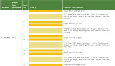
To facilitate this understanding, it’s essential to employ visual aids such as diagrams and tables. These can present the layout of the PCB in a way that is easily digestible. For instance, a well-structured table can list components alongside their respective locations and specifications:
| Component Type | Designator | Location |
|---|---|---|
| Resistor | R1 | 5mm x 10mm |
| Capacitor | C1 | 20mm x 30mm |
| Integrated Circuit | U1 | 50mm x 50mm |
Such tables serve as valuable references during the assembly process, reducing ambiguity for team members who may be following your instructions. Moreover, utilizing bold text for important specifications and italics for critical notes enhances readability and comprehension.
Thoroughness in translating these designs not only supports the assembly team but also plays a vital role in minimizing errors that could lead to costly redesigns or assembly failures. By ensuring that each instruction is detailed and visually supported, teams can achieve smoother transitions from design to production, ultimately enhancing the overall efficiency of PCBA projects.
Common Mistakes to Avoid in PCB Assembly Drawings
When creating PCB assembly drawings, it is critical to avoid several common pitfalls that can lead to costly errors and inefficiencies in the manufacturing process. One significant mistake is the lack of sufficient detail; omitting important specifications such as component orientation, land patterns, or connection points can cause confusion on the production line. Inconsistent terminology can also create misunderstandings among team members. For example, using abbreviations without definition may lead to misinterpretation by those not familiar with the shorthand. It’s also essential to ensure that all components are clearly labeled; misidentified parts can lead to assembly errors, resulting in extensive rework or scrapping of the PCBA. Furthermore, neglecting to include detailed assembly instructions can hamper the effectiveness of production teams in following the intended design; this includes notes on handling sensitive components and any specific tools required for assembly. Finally, failing to review and validate assembly drawings against updated design files could result in discrepancies that affect product performance. By being aware of these potential mistakes and addressing them proactively, designers and engineers can ensure that their pcb assembly drawings facilitate a smoother transition from design to production, ultimately leading to more successful outcomes in their projects.
Enhancing Collaboration Through Clear Assembly Documentation
Effective pcb assembly relies heavily on robust communication among team members, and clear assembly documentation is vital in achieving this goal. When designers provide precise and unambiguous assembly drawings, it facilitates a seamless exchange of information between the design and production teams. This clarity not only aids in understanding how components fit together but also minimizes the potential for errors during the manufacturing process. By ensuring that assembly instructions are detailed, teams can address ambiguities proactively, which ultimately leads to a more efficient workflow.
It is also essential that teams adopt a standardized format for pcba documentation that everyone can easily understand. This standardization can include consistent symbols, labeling conventions, and measurement units that aid in removing uncertainties. When everyone is on the same page regarding these conventions, teamwork flourishes leading to quicker decision-making and fewer misunderstandings.
“The right documentation can bridge the gap between creativity and execution.”
To further enhance collaboration, incorporating visual aids—such as annotated images or diagrams—can provide additional clarity. An enriching practice could be regular review sessions where assembly documentation is revisited collectively by both designers and manufacturers to ensure alignment on project expectations. Engaging multiple perspectives during these discussions often elicits valuable insights that refine the documentations further.
Ultimately, fostering an environment where open communication about pcb assembly practices is encouraged will not only improve overall productivity but also drive innovation within project teams as they work together to achieve common goals with confidence and clarity.
Practical Tips for Creating Accurate Assembly Drawings
Creating precise assembly drawings is paramount in the realm of PCB assembly or PCBA. One of the foremost tips is to ensure that every component is clearly labeled, including part numbers and specifications that correspond to the design files. This clarity aids in minimizing confusion during the assembly process, reducing potential errors. Additionally, utilizing standardized symbols and nomenclature can significantly enhance understanding among various stakeholders involved in the project. It’s also essential to maintain a consistent layout for your drawings; this consistency allows for easier navigation and comprehension across different projects.
Another key aspect is incorporating measurement references and scales—this practice not only assists in the physical placement of components but also helps in verifying spatial arrangements during assembly. Consider using color coding for different circuit functions; this visual differentiation can effectively guide assemblers through complex designs while improving accuracy. Furthermore, assembling a checklist derived from your drawings can serve as a useful reference during manufacturing, ensuring every phase of the PCB assembly process adheres strictly to approved specifications.
In conclusion, attention to detail in assembly drawings—ranging from clarity and standardization to color coding and reference checks—can significantly enhance overall project outcomes. By employing these practical tips, engineers and designers can elevate their PCBA processes and ensure a smoother transition from design to production.
The Impact of Detailed Drawings on Manufacturing Efficiency
In the realm of pcb assembly, the precision of assembly drawings plays a crucial role in enhancing manufacturing efficiency. Detailed drawings serve as a comprehensive roadmap for assembling printed circuit boards (PCBs), ensuring that every component is accurately placed and soldered. When these drawings are meticulous and well-structured, they minimize the risk of errors during the assembly process, leading to a more streamlined and efficient workflow. This clarity not only aids production teams in understanding the specific requirements but also facilitates improved communication among engineers, designers, and assembly operators. By adhering to precise PCBA standards outlined in assembly drawings, manufacturers can significantly reduce rework and wastage, thereby optimizing resource utilization. Additionally, clear visual instructions help to standardize processes, ensuring that each assembly is conducted with consistent quality and speed. Ultimately, well-detailed assembly drawings do not merely serve as documentation; they are vital tools that contribute directly to enhancing overall manufacturing efficiency and project success.
Case Studies: Successful PCB Projects and Their Assembly Drawings
In examining various pcb assembly projects, it’s evident that well-crafted assembly drawings serve as the backbone of successful implementation. For example, in the development of a consumer electronics device, one team utilized meticulous pcba documentation that outlined every aspect of the assembly process. This attention to detail not only minimized errors but also facilitated seamless communication among engineers and production staff. In another instance, a medical device manufacturer encountered significant challenges during assembly due to inadequate assembly drawing specifications. By revising their drawings to incorporate more explicit instructions and visuals, they improved their workflow and significantly reduced production time. These case studies illustrate that clear and detailed assembly drawings not only enhance the efficiency of pcb assembly processes but also contribute significantly to overall project success. As each project attests, investing time in creating robust assembly documentation can yield substantial returns in reduced rework and elevated quality standards in the final product.
Conclusion
In summary, effective pcb assembly is fundamentally anchored in the quality of assembly drawings. These drawings serve as vital communication tools that help bridge the gap between design and production teams, ensuring that everyone is on the same page. By focusing on clarity and precision in pcba documentation, manufacturers can significantly reduce the potential for errors during assembly. Moreover, accurate assembly drawings can lead to more efficient manufacturing processes, thereby saving time and resources. As we reflect on the intricacies of developing these drawings, one must remember that they are not just technical specifications but also a roadmap for successful project execution. In essence, mastering the art of assembly drawing is crucial to achieving optimal performance in pcb assembly, ultimately enhancing the overall quality and reliability of printed circuit boards.
FAQs
When diving into the world of PCB assembly or PCBA, several questions often arise, especially regarding the nuances of assembly drawings. One common inquiry concerns the purpose and significance of these assembly drawings in achieving an optimal PCB design. It’s essential to understand that these drawings serve as a critical communication tool between design and manufacturing teams, ensuring that every detail is captured with precision. Additionally, many individuals wonder about the specific elements that constitute a successful assembly drawing. The best practices typically include clear labeling of components, accurate measurement specifications, and included annotations that describe any unique assembly instructions.
Another frequent question involves the challenges faced during the PCB assembly process. Assembling PCBs is meticulous work and can lead to errors if not properly documented. Common mistakes include overlooking component placements or failing to provide adequate instructions for complex assemblies. This highlights the necessity for detailed documentation and a thorough review process before moving into production.
Lastly, many readers are curious about how they can improve their own PCB assembly documentation practices. Developing a checklist of key elements to include in their drawings, maintaining consistency across all documents, and regularly seeking feedback from team members can significantly enhance documentation quality. By prioritizing clarity and detail in assembly instructions, one can minimize manufacturing delays and improve overall efficiency.
For more in-depth guidance on enhancing your factories’ PCB projects through effective PCB assembly practices, please click here: Andwin PCB Assembly.