Mastering the Art of Assembly Circuit Design: A Comprehensive Guide
Key Takeaways
Understanding the intricacies of assembly circuit design is crucial for creating reliable and high-performing electronic devices. This comprehensive guide provides invaluable insights into the step-by-step techniques and practical tips necessary for mastering the art. From learning essential principles and theories to selecting the right components for your pcb assembly (PCBA) needs, this resource covers it all. Creating and interpreting schematic diagrams become second nature with our clear explanations, allowing you to transition smoothly to hands-on assembly techniques. Additionally, you’ll gain expertise in troubleshooting common issues, ensuring your designs are both performant and dependable. By optimizing circuit designs based on detailed principles outlined in this guide, you can push the boundaries of innovation in your projects. Embrace advanced tips and practical applications featured in this resource to achieve excellence in pcba endeavors.
Introduction to Assembly Circuit Design
In the world of assembly circuit design, both beginners and seasoned engineers can find a fulfilling challenge that blends theoretical understanding with practical application. This comprehensive guide will aid you in navigating the complex yet fascinating domain of PCB Assembly (pcba). From understanding essential principles to selecting the right components, you will be equipped with the knowledge needed for effective circuit assembly.
Tip: Always double-check your component values and orientations before soldering to avoid common assembly errors.
A solid introduction to assembly circuit design begins with grasping basic concepts like current flow, voltage levels, and circuit functionalities. You must also become familiar with schematic diagrams, which serve as blueprints for your circuit layouts. These diagrams not only depict the connections between different components but also indicate signal paths and power distribution.
Furthermore, understanding PCB layout design is paramount to achieving successful assembly. The layout phase involves arranging components on the PCB in a manner that optimizes both space and performance.
“The key to a reliable PCB Assembly (pcba) lies in meticulous planning and a thorough understanding of schematic diagrams.”
Below is an example table outlining essential tools needed for assembly:
| Tool | Purpose |
|---|---|
| Soldering Iron | Attaching components to the PCB |
| Multimeter | Measuring voltage, current, and resistance |
| Oscilloscope | Viewing signal waveforms |
| Tweezers | Handling small components |
Starting with these basics ensures that you build a strong foundation in assembly circuit design, setting you up for success as you delve deeper into more complex topics such as troubleshooting and optimization.
Essential Principles and Theories in Circuit Assembly
Understanding the essential principles and theories in circuit assembly is crucial for designing effective electronic systems. One must first grasp the fundamental concepts of current, voltage, and resistance, which form the backbone of any electronic circuit. These concepts are interrelated through Ohm’s Law, which serves as a foundational principle in electronics. Additionally, principles such as Kirchhoff’s Voltage and Current Laws help in analyzing complex circuits by providing rules for how voltages and currents are distributed within a circuit.
When it comes to PCB assembly (Printed Circuit Board assembly or PCBA), one needs to be proficient in translating theoretical knowledge into practical applications. This involves understanding how different components interact within a circuit, such as resistors, capacitors, inductors, and integrated circuits. The layout of these components on a PCB must follow best practices to ensure signal integrity and minimize interference.
Effective circuit assembly also requires knowledge of soldering techniques and the ability to interpret schematic diagrams accurately. The choice of materials, including the type of solder and flux used, plays a vital role in ensuring reliable electrical connections. Moreover, understanding thermal management is essential for preventing overheating and ensuring the longevity of components.
By mastering these essential principles and theories, one can not only create functional circuits but also optimize them for efficiency and reliability. This foundational knowledge serves as the stepping stone to more advanced circuit design techniques, paving the way for innovative applications in various electronics fields.
Selecting the Right Components for Your Circuit
When embarking on the journey of pcb assembly and pcba, selecting the right components is crucial to ensure the success of your circuit design. Start by understanding the specific requirements of your project, such as voltage, current, and power ratings. Choose components that not only meet these specifications but also offer reliability and longevity. Consider factors like tolerance, temperature coefficient, and package type when selecting resistors, capacitors, and semiconductors. It’s also essential to source your components from reputable suppliers to avoid issues with counterfeit parts.
For integrated circuits (ICs), ensure compatibility with your circuit’s design and verify that they can handle the necessary data processing speeds. When dealing with passive components like inductors and transformers, pay attention to their inductance values and current-carrying capabilities. In addition to electrical properties, evaluate physical dimensions to confirm they fit within your pcb assembly layout.
To streamline this process, use component libraries provided by Electronic Design Automation (EDA) tools which can offer detailed datasheets and footprints for precise placement. Moreover, always keep a close eye on the availability of equivalents or alternative parts in case of supply chain disruptions.
In conclusion, meticulous selection of each component ensures operational efficiency and durability of your assembly circuit projects. Prioritize specifications, reliability, sourcing authenticity, and compatibility to master the art of component selection in pcba.
Creating and Interpreting Schematic Diagrams
Understanding how to create and interpret schematic diagrams is a pivotal skill in assembly circuit design. A schematic diagram represents the blueprint of your circuit, showcasing the components and their interconnections in a clear and organized manner. To get started, you need to familiarize yourself with standard symbols used in electronic diagrams, such as resistors, capacitors, transistors, and other essential elements. These symbols serve as a universal language that enables engineers worldwide to understand and replicate circuits with ease.
When drafting a schematic, it’s crucial to keep clarity at the forefront. Position your components logically and minimize wire crossings as much as possible. Label each component accurately with its reference designator and value to aid both in pcb assembly (Printed Circuit Board Assembly) and troubleshooting later stages. Additionally, cross-referencing is vital; ensure that each part on your schematic matches its corresponding part on the bill of materials (BOM).
For those involved in PCBA, schematic diagrams facilitate efficient communication between design and assembly teams. By providing a detailed visual representation of the circuit layout, these diagrams help identify connection points for soldering components onto the PCB. Moreover, they play an essential role during the testing phase by pinpointing potential issues based on signal flow paths.
Interpreting schematics requires a methodical approach: start by identifying power sources and ground connections, then trace how signals move through various components. Understanding these pathways can significantly streamline the diagnosis of any operational issues.
Whether you are embarking on your first project or improving an existing design, mastering the art of creating accurate schematic diagrams ensures your circuits are reliable and perform optimally. Detailed schematics paired with precise component placement can transform complex ideas into tangible results in the world of circuit assembly.
Hands-On Assembly Techniques and Best Practices
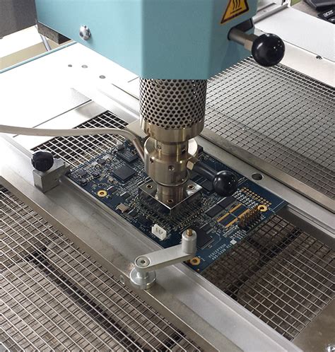
When embarking on pcb assembly, adhering to certain hands-on techniques and best practices is crucial for ensuring both reliability and performance of your circuit. Begin by organizing your workspace, keeping all tools and components within easy reach. Accurate component placement is essential; using a component placement plan can minimize errors. Soldering is a fundamental skill in pcba; use the right type of solder and ensure proper heat application to avoid damaging the circuit board.
Always inspect solder joints meticulously for cold joints or bridges, which could lead to electrical failures. Flux can be used to clean the surfaces for better solder adhesion. For surface-mount devices (SMDs), investing in a quality microscope can help achieve precise results. Efficient heat management—through the use of heat sinks or thermal vias—can prolong the life of your components by preventing overheating.
Testing each section of the assembled circuit independently before completing the whole assembly can save time in troubleshooting later on. Utilize multimeters, oscilloscopes, and other diagnostic tools to verify functionality at each stage. Clean your assembled pcba thoroughly with isopropyl alcohol or specialized cleaning solutions to remove any residual flux or debris.
Attention to detail in these practices not only enhances the assembly process but also significantly impacts the overall reliability and performance of your final design. By mastering these hands-on techniques, you’ll ensure a higher quality end product every time you engage in pcb assembly.
Troubleshooting Common Issues in Circuit Assembly
In the realm of pcb assembly, encountering issues during the assembly process is not uncommon. One of the most frequent problems is poor solder joints, which can manifest as cold joints or cracked connections. This often results from improper soldering techniques or insufficient heat during the process. Ensuring components are securely attached to the board requires meticulous pcba practices — applying the right amount of solder and correct heating can mitigate these issues.
Another prevalent issue is component misplacement, where parts are incorrectly aligned or oriented on the board. This can be resolved by double-checking schematic diagrams and ensuring each component matches its designated pads before soldering. Additionally, electrostatic discharge (ESD) can damage sensitive components, leading to circuit failures. Using ESD-safe tools and environment controls becomes crucial in protecting your assembly from unintended static charges.
Short circuits are another common headache, often caused by traces crossing over unintended areas or excessive solder bridging two points that should remain isolated. Careful inspection using magnification tools and continuity testers helps identify and rectify short circuits before powering up your design.
Lastly, intermittent connections—those that work sporadically—can stem from a variety of factors including loose headers or connectors that aren’t fully seated. Regularly inspecting physical connections and applying conformal coatings where necessary enhances long-term reliability.
In addressing these troubleshooting challenges, harnessing a systematic approach—observing symptoms, identifying potential causes, testing solutions—is vital to maintaining robust and efficient pcba processes.
Optimizing Circuit Designs for Performance and Reliability
When optimizing circuit designs for performance and reliability, several critical factors come into play. One fundamental aspect is the careful layout of the PCB assembly (PCBA), which ensures that components are placed strategically to minimize noise and signal interference. Utilizing high-quality components and adhering to strict manufacturing standards can significantly enhance the circuit’s overall performance. Thermal management is another crucial consideration; efficient heat dissipation through proper placement of heat sinks and use of low thermal resistance materials can prevent overheating and extend the lifespan of your PCBA.
Effective signal integrity testing also plays an essential role; verifying that signals maintain their quality without distortion or unwanted crosstalk is paramount for reliable operation. Furthermore, incorporating redundant design elements such as backup power paths or fail-safe mechanisms can boost the robustness of your circuits.
By optimizing these elements—component layout, thermal management, signal integrity, and redundant designs—you can achieve a high-performing and reliable PCB assembly capable of enduring rigorous operational demands. This holistic approach ensures that your circuits not only meet specification requirements but also perform consistently under variable conditions.
Advanced Tips and Practical Applications in Assembly Circuit Design
To truly excel in assembly circuit design, understanding some advanced tips and practical applications is crucial. These techniques not only enhance the functionality of your designs but also ensure their long-term reliability. One essential aspect is the integration of PCB assembly (PCBA) strategies, which streamline the entire process from schematic creation to final product realization. For instance, using automated pick-and-place machines can significantly speed up assembly time while maintaining high accuracy rates.
Another critical component is the selection of materials. Opting for high-quality substrates and solder can prevent common issues such as poor connectivity and short circuits. Additionally, incorporating thermal management solutions like heat sinks or thermal vias can improve the performance of your circuits by preventing overheating.
Moreover, it’s prudent to employ design-for-manufacture (DFM) principles. This involves making your designs as production-friendly as possible, which reduces costs and minimizes errors during assembly. Implementing robust testing protocols, such as in-circuit testing (ICT) and functional testing, ensures that any defects are identified early on, thus saving time and resources.
Practical applications extend beyond just the technical aspects. Familiarizing yourself with industry standards such as IPC-A-610 for electronic assemblies can provide benchmarks for quality assurance. Additionally, leveraging simulation tools to predict circuit behavior under varying conditions can lead to more optimized designs.
Incorporating these advanced tips not only makes the PCBA process more efficient but also uplifts overall product quality, making your circuit designs resilient and reliable in various applications.
Conclusion
In mastering the art of assembly circuit design, enthusiasts and professionals alike can elevate their skills by focusing on the crucial aspects covered in this guide. From understanding the essential principles and theories to selecting suitable components, each step is pivotal. Crafting and interpreting schematic diagrams provide a solid foundation, while hands-on assembly techniques bring designs to life. Navigating and troubleshooting pcb assembly effectively ensures reliable performance. Moreover, optimizing your designs enhances both efficiency and durability. Embracing these comprehensive insights equips you with the capability to tackle pcba challenges confidently, making your circuit assembly journey both rewarding and successful.
FAQs
When diving into the world of PCB assembly and PCBA, many questions often arise, especially for those who are new to circuit design. Here are some frequently asked questions to help you navigate through the complexities of assembly circuit design.
What is the difference between PCB and PCBA?
A PCB refers to a printed circuit board, which is the blank board that serves as the foundation for electronic components. On the other hand, PCBA stands for printed circuit board assembly, which includes the soldered components on the PCB, turning it into a fully functional board.
What are some common issues encountered during PCB assembly?
Some typical challenges include soldering defects, incorrect component placement, and short circuits. Learning proper hands-on techniques and applying reliable best practices can help mitigate these issues effectively.
How can I ensure the reliability and performance of my assembled circuit?
Optimization begins with thorough schematic creation and component selection. Additionally, incorporating design-for-manufacturing (DFM) principles can enhance both reliability and performance. Detailed troubleshooting during testing stages is also crucial.
For a comprehensive resource detailing step-by-step techniques, practical tips, and essential principles in assembling PCBs, please explore our guide by clicking here. This will provide you with a robust foundation in mastering assembly circuit design.