metal core pcb datasheet
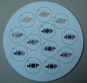
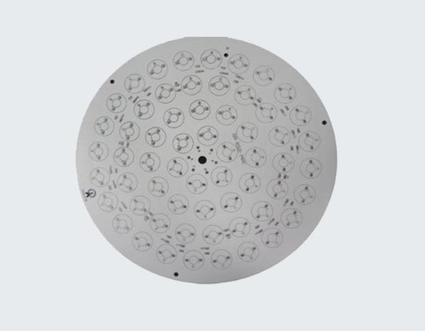
Metal Core PCBs (MCPCBs) are a type of printed circuit board
that are designed to dissipate heat more effectively than traditional PCBs.
They are commonly used in high-power LED lighting, power supplies,
and other applications that generate a significant amount of heat.
In this article, we will provide a comprehensive guide to the metal core PCB datasheet,
including the key specifications and features to look for when selecting an MCPCB.
What is a Metal Core PCB?
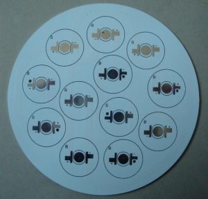
A metal core PCB is a type of printed circuit board that has a metal core,
typically made of aluminum or copper, which serves as a heat sink to dissipate heat generated
by the components on the board. The metal core is sandwiched between layers of insulating material,
typically FR4 or polyimide, which provide electrical isolation and mechanical support for the components.
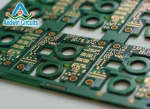
The metal core PCB is designed to provide superior thermal performance compared to traditional PCBs,
which rely on the copper traces and vias to dissipate heat.
The metal core PCB is particularly well-suited for high-power applications,
where the heat generated by the components can cause damage or reduce the lifespan of the components.
Key Specifications and Features of Metal Core PCB Datasheet
When selecting a metal core PCB, there are several key specifications and features to consider. These include:
1. Metal Core Material: The metal core material is one of the most important specifications to consider
when selecting a metal core PCB. The most common materials used for metal core PCBs are aluminum and copper,
with aluminum being the most popular due to its low cost and good thermal conductivity.
Copper is more expensive but has a higher thermal conductivity, making it better suited for high-power applications.
2. Thermal Conductivity: The thermal conductivity of the metal core material is another important specification to consider.
The thermal conductivity determines how effectively the metal core can dissipate heat generated by the components on the board.
Aluminum has a thermal conductivity of around 200 W/mK, while copper has a thermal conductivity of around 400 W/mK.
3. Dielectric Material: The dielectric material is the insulating layer
that separates the metal core from the copper traces and vias.
The most common dielectric materials used for metal core PCBs are FR4 and polyimide.
FR4 is a low-cost material that provides good electrical isolation and mechanical support,
while polyimide is more expensive but provides better thermal performance and higher temperature resistance.
4. Copper Thickness: The copper thickness is another important specification to consider.
The copper thickness determines the current-carrying capacity of the traces and vias on the board.
The most common copper thicknesses for metal core PCBs are 1 oz and 2 oz,
with 2 oz being better suited for high-power applications.
5. Surface Finish: The surface finish is the final coating applied to the copper traces and vias on the board.
The most common surface finishes for metal core PCBs are HASL, ENIG,
and OSP. HASL is a low-cost finish that provides good solderability,
while ENIG and OSP are more expensive but provide better performance and higher reliability.
Conclusion
Metal core PCBs are an important type of printed circuit board
that are designed to provide superior thermal performance compared to traditional PCBs.
When selecting a metal core PCB, it is important to consider the key specifications and features,
including the metal core material, thermal conductivity,
dielectric material, copper thickness, and surface finish.
By carefully considering these factors,
you can select the right metal core PCB for your application and ensure optimal performance and reliability.

