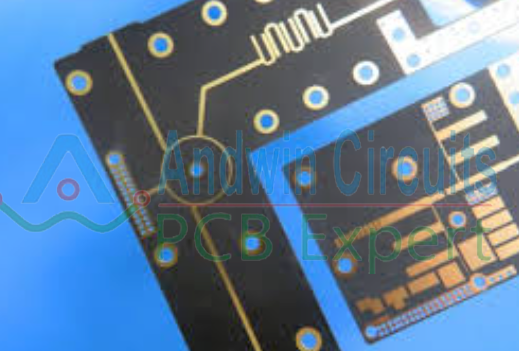
metal core pcb design
Metal core PCBs, also known as MCPCBs, are a type of printed circuit board that uses a metal core as the base material instead of the traditional FR4 substrate. These boards are commonly used in high-power LED lighting, automotive electronics, power supplies, and other applications where heat dissipation is a critical factor.
Designing a metal core PCB requires careful consideration of various factors to ensure optimal performance and reliability.
In this article, we will discuss some key guidelines for designing metal core PCBs.
Thermal Management:
One of the primary reasons for using metal core PCBs is their superior thermal conductivity compared to traditional FR4 boards.
The metal core helps to dissipate heat generated by components more efficiently, reducing the risk of overheating and improving overall reliability.
When designing a metal core PCB, it is essential to consider the thermal properties of the metal core material,
And ensure that it can effectively transfer heat away from critical components.
Component Placement:
Proper component placement is crucial in metal core PCB design to ensure optimal heat dissipation and electrical performance.
High-power components that generate a significant amount of heat should be placed near the center of the board,
where the metal core can efficiently transfer heat away.
It is also essential to avoid placing components too close together, as this can hinder airflow and lead to localized overheating.
Trace Routing:
When routing traces on a metal core PCB, it is essential to consider the thermal conductivity of the metal core material. Copper is commonly used for traces on metal core PCBs due to its high conductivity, but care must be taken to ensure that the traces are adequately sized to carry the required current without overheating. Additionally, it is recommended to use wider traces and larger vias to improve heat dissipation and reduce the risk of thermal issues.
Ground Plane Design:
A solid ground plane is essential for proper signal integrity and EMI/EMC performance in metal core PCBs. The ground plane should be connected to the metal core to provide a low-impedance path for return currents and help dissipate heat. It is also recommended to use multiple ground vias to connect the ground plane to the metal core, ensuring a reliable electrical connection and efficient heat transfer.
Thermal Vias:
Thermal vias are an essential component of metal core PCB design, as they help to transfer heat from the components to the metal core. These vias should be strategically placed near high-power components and thermal pads to ensure effective heat dissipation. It is recommended to use a sufficient number of thermal vias and ensure that they are properly sized to maximize heat transfer.
Insulation:
Since metal core PCBs have a conductive metal core, it is crucial to provide adequate insulation to prevent short circuits and ensure electrical safety. Insulating layers such as thermally conductive dielectric materials or thermal interface materials can be used to isolate the metal core from the components and traces. Care should be taken to select insulation materials with appropriate thermal conductivity and dielectric strength for the application.
Testing and Validation:
Once the metal core PCB design is complete, it is essential to conduct thorough testing and validation to ensure that the board meets the required performance specifications. Thermal testing, electrical testing, and reliability testing should be performed to verify the functionality and reliability of the PCB under operating conditions. Any issues or deficiencies identified during testing should be addressed promptly to prevent potential failures in the field.
In conclusion, designing a metal core PCB requires careful consideration of thermal management, component placement, trace routing, ground plane design, thermal vias, insulation, and testing. By following these guidelines and best practices, designers can create metal core PCBs that deliver optimal performance, reliability, and thermal efficiency in high-power applications.
Metal Core PCBs, also known as MCPCBs, are printed circuit boards with a metal core that
provides excellent thermal conductivity. They are commonly used in high-power LED lighting,
power electronics, and automotive applications. Designing an MCPCB requires careful
consideration of the thermal management, electrical performance, and mechanical stability.
In this article, we will provide a comprehensive guide for designing metal core PCBs for a
production run of 3500PCS.
1. Choose the Right Metal Core Material
The metal core material is the foundation of an MCPCB. It provides the thermal conductivity
that allows the PCB to dissipate heat efficiently. The most commonly used metal core
materials are aluminum, copper, and brass. Aluminum is the most popular choice due to its
high thermal conductivity, low cost, and lightweight. Copper has better thermal
conductivity than aluminum but is more expensive and heavier. Brass is a good compromise
between aluminum and copper but is less common.

When choosing the metal core material, consider the thermal requirements of your
application, the size and weight constraints, and the cost. For a production run of
3500PCS, it is recommended to use a standard metal core material that is readily available
and affordable.
2. Determine the Thermal Requirements
The thermal requirements of your application will dictate the thickness of the metal core
and the thermal vias needed. Thermal vias are small holes drilled through the metal core to
allow heat to transfer from the PCB to the metal core. The number and size of thermal vias
depend on the thermal conductivity of the metal core material and the power dissipation of
the components.
To determine the thermal requirements, calculate the maximum temperature rise of the PCB
and the maximum power dissipation of the components. Use a thermal simulation software to
model the heat flow and optimize the thermal design. For a production run of 3500PCS, it is
recommended to perform a thermal validation test on a prototype to ensure the thermal
performance meets the requirements.

3. Optimize the Electrical Performance
The electrical performance of an MCPCB is as important as the thermal performance. The
metal core can act as a ground plane or a power plane, depending on the circuit design. The
metal core can also affect the signal integrity and the electromagnetic interference (EMI)
performance.
To optimize the electrical performance, follow the standard PCB design guidelines for trace
width, spacing, and impedance control. Use a signal integrity simulation software to
analyze the high-speed signals and optimize the signal integrity. Use an EMI simulation
software to analyze the EMI performance and optimize the shielding.
4. Ensure Mechanical Stability
The metal core provides mechanical stability to the PCB, but it can also cause mechanical
stress if not properly designed. The metal core can expand and contract due to temperature
changes, which can cause the PCB to warp or crack. The metal core can also affect the
solder joint reliability and the component placement.

To ensure mechanical stability, follow the standard PCB design guidelines for board
thickness, hole size, and component placement. Use a mechanical simulation software to
analyze the stress and strain of the PCB and optimize the mechanical design. Use a
reliability test to validate the solder joint reliability and the component placement.
Conclusion
Designing metal core PCBs requires careful consideration of the thermal management,
electrical performance, and mechanical stability. By choosing the right metal core
material, determining the thermal requirements, optimizing the electrical performance, and
ensuring mechanical stability, you can design an MCPCB that meets the requirements of your
application. For a production run of 3500PCS, it is recommended to perform a prototype
validation test and a reliability test to ensure the quality and consistency of the PCBs.