Metal Core PCB Prototypes: Advanced Heat Dissipation Solutions
Key Takeaways
When exploring metal core PCB prototypes, understanding their engineering advantages helps you make informed decisions for high-power applications. These specialized boards use aluminum or copper substrates to address thermal challenges that traditional PCB manufacturing methods struggle with. Here’s what you need to know:
Thermal Efficiency: Metal cores transfer heat 8–10 times faster than FR4, reducing hot spots in LED arrays or power converters.
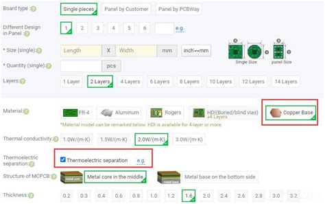
Material Selection: Property Aluminum Core Copper Core Thermal Conductivity 150-220 W/mK 380-400 W/mK Weight Lighter 30% Heavier PCB Manufacturing Cost $0.8–$1.2/sq.in $1.5–$2.5/sq.in Copper excels in extreme environments, while aluminum balances cost and performance for mid-power systems.
Design Optimization: Partnering with experienced PCB manufacturing companies ensures proper dielectric layer thickness and component placement. For example, doubling the copper layer thickness (1 oz → 2 oz) can lower junction temperatures by 12–15°C in LED drivers.
“The choice between aluminum and copper directly impacts both thermal performance and project budgets. Always simulate heat distribution before finalizing prototypes.” — Thermal Engineer at Andwin PCB.
- Cost-Benefit Insights: While PCB manufacturing business expenses rise by 20–35% for metal cores, they extend product lifespans by 2–3× in high-temperature environments. This tradeoff is critical for automotive or industrial applications where reliability outweighs upfront costs.
For startups, collaborating with PCB manufacturing specialists helps navigate complexities like anodization for corrosion resistance or laser drilling for precision vias. Prioritize vendors offering thermal simulation tools to validate designs before production.
By integrating these takeaways early, you avoid costly redesigns and ensure your prototypes meet stringent thermal benchmarks. Next, we’ll dissect how aluminum and copper cores perform in real-world stress tests.
Metal Core PCB Prototypes: Engineering Thermal Efficiency in High-Power Applications
When designing high-power electronics, thermal management isn’t just an afterthought—it’s a foundational requirement. Metal core PCB prototypes address this challenge by integrating thermally conductive substrates like aluminum or copper, which outperform traditional FR4 materials by 10-20x in heat dissipation. This makes them indispensable for applications where heat buildup threatens performance, from motor controllers to power converters.
The choice of substrate material directly impacts thermal efficiency. Aluminum cores, for instance, offer a balance of affordability and conductivity, making them popular for LED lighting systems. Copper cores, while costlier, provide unmatched thermal transfer for high-frequency RF devices or automotive power modules. When collaborating with PCB manufacturing companies, you’ll need to specify material properties early in the design phase to align thermal performance with operational demands.
One critical advantage of metal core PCBs lies in their layered structure. A dielectric layer sandwiched between the metal base and circuit layer ensures electrical isolation while enabling rapid heat transfer away from sensitive components. This design reduces hotspots, extending the lifespan of high-power ICs and minimizing the need for bulky heatsinks. For startups in the PCB manufacturing business, prototyping with metal cores can reveal cost-saving opportunities by optimizing board layouts for thermal flow.
However, PCB manufacturing cost considerations remain pivotal. While metal core prototypes may have higher initial expenses than FR4 boards, their long-term reliability in extreme conditions often justifies the investment. For example, a 2mm aluminum-core PCB might cost 30-50% more than a standard FR4 equivalent, but it can reduce thermal-related failures by over 60% in high-current applications.
To maximize efficiency, engineers should prioritize:
- Minimizing thermal resistance through precise via placement
- Selecting dielectric materials with high thermal conductivity (>2.5 W/mK)
- Partnering with PCB manufacturing specialists experienced in high-power designs
By addressing these factors early, you create prototypes that not only solve immediate thermal challenges but also scale effectively for mass production. Whether developing industrial motor drives or next-gen EV charging systems, metal core PCBs provide the thermal backbone that keeps high-power electronics running cooler—and longer.
How Metal Core Substrates Revolutionize Heat Management in Electronics
When designing high-power electronics, managing heat isn’t just an afterthought—it’s a critical factor defining your product’s reliability. Traditional FR4 substrates struggle to dissipate heat efficiently, leading to performance throttling or even premature component failure. This is where metal core PCBs (MCPCBs) step in, leveraging materials like aluminum or copper to redirect heat away from sensitive components. By integrating a thermally conductive metal layer—often 5–10 times more effective than standard substrates—these boards actively channel heat to designated cooling zones, ensuring stable operation even under extreme loads.
For PCB manufacturing companies, the shift to metal core substrates represents a strategic upgrade. Aluminum cores, for instance, offer a balance of affordability and thermal conductivity (1.5–3 W/m·K), making them ideal for LED lighting systems or automotive electronics. Copper cores, while costlier, deliver superior conductivity (up to 400 W/m·K), perfect for aerospace or industrial power converters. The PCB manufacturing cost for MCPCBs has dropped significantly in recent years, thanks to optimized production processes like laser drilling and advanced lamination techniques. This makes them accessible even for mid-volume projects, challenging the notion that thermal efficiency must come at a premium.
Your design choices here ripple across the entire PCB manufacturing business. By opting for metal cores, you reduce reliance on external heat sinks, slashing assembly complexity and material overhead. Thermal vias and dielectric layers in MCPCBs further refine heat pathways, allowing precise control over temperature distribution. For example, in high-brightness LED arrays, this precision prevents “thermal runaway,” where localized overheating dims output or cuts lifespan.
Transitioning to metal cores also future-proofs your designs. As power densities climb in 5G infrastructure and electric vehicles, the ability to manage heat without bulky cooling systems becomes a competitive edge. While PCB manufacturing for metal cores demands tighter tolerances—like managing coefficient of thermal expansion (CTE) mismatches—the long-term gains in reliability and performance justify the upfront engineering effort.
In essence, metal core substrates aren’t just solving a thermal challenge—they’re redefining how you approach durability and efficiency in modern electronics. The next section explores how material selection between aluminum and copper impacts these outcomes, ensuring you align thermal performance with project requirements.
Aluminum vs Copper Core PCBs: Choosing the Right Material for Thermal Performance
When selecting a metal core PCB for your project, the choice between aluminum and copper substrates hinges on balancing thermal efficiency, mechanical requirements, and PCB manufacturing cost. Aluminum cores, with their thermal conductivity of 150-200 W/mK, offer a lightweight and cost-effective solution for moderate heat dissipation needs. They’re widely used in LED lighting systems or consumer electronics where weight reduction and affordability are priorities. However, copper cores deliver nearly double the thermal conductivity (400 W/mK), making them indispensable for high-power applications like automotive inverters or industrial motor drives where rapid heat transfer is critical.
PCB manufacturing companies often recommend aluminum for projects with tight budgets, as its material and processing costs are 30-50% lower than copper. But don’t let upfront savings overshadow long-term performance: copper’s superior heat dissipation can reduce the need for additional cooling components, potentially lowering total system costs in power-dense designs. For instance, in high-power LED arrays or server power supplies, copper’s ability to handle sustained thermal loads minimizes the risk of premature failure, justifying its higher initial investment.
Mechanical considerations also play a role. Aluminum’s lower density makes it ideal for portable devices, while copper’s rigidity suits applications requiring structural stability. When prototyping, collaborate closely with your PCB manufacturing business partner to simulate thermal pathways—copper may allow for thinner dielectric layers, improving heat transfer but increasing complexity in multilayer designs.
Transitioning from material selection to production, factor in PCB manufacturing constraints. Aluminum’s easier machinability speeds up prototyping, whereas copper demands specialized tooling, extending lead times. Yet, for mission-critical systems like aerospace controls or medical imaging devices, copper’s unmatched thermal performance often outweighs these delays.
Ultimately, the decision aligns with your project’s thermal budget, operational environment, and scalability goals. Whether prioritizing cost efficiency with aluminum or maximizing heat dissipation with copper, partnering with experienced PCB manufacturing companies ensures your prototype meets both performance benchmarks and economic realities.
Designing Effective MCPCB Prototypes: Best Practices for Heat Dissipation
When developing metal core PCB prototypes, thermal management isn’t just an afterthought—it’s the cornerstone of reliable performance. While material selection (like aluminum or copper substrates) sets the baseline, your design choices ultimately determine how effectively heat spreads away from critical components. Start by optimizing the thermal pathway: position high-power devices directly over the metal core’s exposed regions, minimizing thermal resistance between heat sources and the substrate.
Trace routing plays a pivotal role—pcb manufacturing companies often recommend widening power traces and using thicker copper layers (2 oz. or more) to reduce joule heating. However, balancing this with pcb manufacturing cost constraints requires strategic planning. For instance, selective copper thickening in high-current areas, rather than full-layer upgrades, maintains thermal efficiency without inflating budgets.
Layer stackup configuration is equally critical. A low-thermal-resistance dielectric layer (like 75-100 μm) enhances heat transfer from the circuit layer to the metal core. Pair this with thermal vias—arrayed beneath hot components—to create vertical heat dissipation channels. Every micrometer matters: improper dielectric thickness can bottleneck thermal flow, negating the metal core’s advantages.
Collaborate early with your pcb manufacturing partner to validate thermal simulations. Advanced tools like finite element analysis (FEA) predict hotspot behavior under real-world loads, allowing iterative adjustments before prototyping. This proactive approach avoids costly redesigns and aligns with lean pcb manufacturing business practices.
Don’t overlook surface finish compatibility. While HASL (Hot Air Solder Leveling) is cost-effective, immersion silver or ENEPIG coatings offer better thermal stability for repeated thermal cycling. Additionally, ensure component placement avoids "thermal shadows"—areas where adjacent parts block airflow or heat dissipation.
Finally, prototype testing should mirror operational extremes. Monitor thermal gradients using infrared cameras and validate that maximum temperatures stay 15-20% below component ratings. Remember: a well-designed MCPCB prototype isn’t just about surviving heat—it’s about thriving under it, ensuring longevity for high-power LEDs, motor drives, or automotive systems. By integrating these practices, you transform raw materials into engineered solutions that outperform traditional FR4 alternatives.
LED Systems and Beyond: Key Applications of Metal Core PCB Technology
When designing high-intensity LED systems, managing heat isn’t just an option—it’s a survival requirement. Metal core PCBs (MCPCBs) excel here, leveraging aluminum or copper substrates to channel heat away from sensitive components. This thermal efficiency allows LEDs to operate at 70% higher luminous efficacy compared to traditional FR4 boards, extending lifespan while reducing energy waste. But the story doesn’t end with lighting.
In automotive electronics, PCB manufacturing companies rely on metal core prototypes to power everything from headlights to battery management systems. The substrate’s thermal conductivity prevents overheating in confined spaces, ensuring reliability even in extreme temperature cycles. Similarly, industrial motor drives and solar inverters benefit from direct heat transfer to heatsinks, minimizing performance throttling during sustained operation.
Cost considerations? While PCB manufacturing cost for metal cores is initially 20-30% higher than FR4, the long-term savings in reduced cooling hardware and fewer failures justify the investment. For high-power RF amplifiers or server power supplies, this trade-off becomes a no-brainer. PCB manufacturing business strategies increasingly prioritize MCPCBs for these applications, as clients demand solutions that balance thermal resilience with compact designs.
Emerging sectors like aerospace and medical imaging are pushing boundaries too. Hyperspectral imaging systems, for instance, use copper-core boards to dissipate heat from densely packed sensor arrays without adding bulk. When selecting a partner for prototyping, prioritize PCB manufacturing specialists with expertise in material-specific DFM (Design for Manufacturability). Their input ensures optimal trace layouts and dielectric layer thicknesses, which are critical for maximizing thermal performance without compromising signal integrity.
The shift toward metal cores reflects a broader industrial trend: electronics aren’t just getting smarter—they’re running hotter. Whether you’re retrofitting legacy LED arrays or developing next-gen EV charging stations, MCPCBs offer a scalable thermal foundation. By aligning your designs with material science advancements and production best practices, you unlock systems that perform reliably under pressure—literally and thermally.
Thermal Analysis of Metal Core Prototypes: Ensuring Reliability in Extreme Conditions
When developing metal core PCB prototypes, thermal analysis isn’t just a technical checkbox—it’s the backbone of ensuring your design survives real-world stress. Unlike traditional FR4 boards, metal core substrates (like aluminum or copper) excel at redirecting heat away from sensitive components, but their performance hinges on precise thermal modeling. This process evaluates how heat propagates across layers, identifies potential hotspots, and validates whether your chosen core material meets the thermal demands of your application.
For PCB manufacturing companies, this stage often involves advanced simulation tools such as infrared thermography or computational fluid dynamics (CFD). These methods map temperature gradients under simulated extreme conditions—think sustained high-current loads or ambient temperatures exceeding 85°C. For instance, an aluminum core PCB might show a 20–30% faster heat dissipation rate than FR4 in LED arrays, but a copper core could reduce thermal resistance by another 15% in motor control systems. The choice directly impacts PCB manufacturing cost, as copper’s superior conductivity comes with higher material expenses.
To optimize reliability, designers must balance three factors:
- Thermal conductivity of the metal substrate (measured in W/m·K)
- Dielectric layer thickness, which affects insulation and heat transfer efficiency
- Component placement strategies to minimize thermal interference
For high-power applications like automotive electronics or industrial drives, even a 5°C overshoot in junction temperature can slash component lifespan by half. Rigorous thermal analysis helps avoid this by validating whether your prototype’s design aligns with the operational parameters of end-use environments.
However, partnering with experienced PCB manufacturing businesses is critical. They’ll guide you through trade-offs—like when to use cost-effective aluminum versus ultra-conductive copper—or how dielectric materials influence both electrical isolation and thermal performance. This collaboration ensures your prototype isn’t just functional in lab conditions but thrives where it matters most: in the field.
By prioritizing thermal analysis early in the PCB manufacturing process, you mitigate risks of thermal runaway and ensure your metal core prototype delivers consistent performance—even when pushed to its limits.
Cost-Benefit Breakdown: Metal Core PCBs vs Traditional FR4 Solutions
When evaluating PCB manufacturing options for high-power applications, understanding the financial and performance trade-offs between metal core PCBs and traditional FR4 substrates is critical. While FR4 solutions often appear cheaper upfront, their limitations in thermal management can lead to hidden costs over time—especially in systems requiring sustained heat dissipation.
For starters, PCB manufacturing cost for metal core boards is typically 20-40% higher than FR4 due to specialized materials like aluminum or copper cores. However, this initial investment offsets long-term expenses. For example, high-power LED modules or automotive electronics using FR4 may require additional cooling components (e.g., heat sinks or fans), increasing assembly complexity and maintenance costs. Metal core PCBs, with their integrated thermal conductivity, eliminate these add-ons, reducing PCB manufacturing business overheads by up to 30% in volume production.
The choice also impacts reliability. FR4 substrates suffer from thermal expansion mismatches under prolonged heat exposure, risking solder joint failures. In contrast, metal core designs maintain stability at temperatures exceeding 140°C, slashing warranty claims and replacement cycles. This durability makes them a cost-effective option for industries like aerospace or industrial automation, where downtime is prohibitively expensive.
When partnering with PCB manufacturing companies, consider scalability. While FR4 is ideal for low-to-mid-volume runs, metal core PCBs become more economical at scale due to reduced post-processing steps. Advanced manufacturers can further optimize costs by combining hybrid designs—using FR4 for non-critical layers and metal cores only where heat dissipation matters.
Ultimately, the decision hinges on your application’s thermal demands. If your project involves high-density power circuits or prolonged operational stress, the higher PCB manufacturing cost of metal cores pays dividends in performance longevity. For less demanding applications, FR4 remains a viable, budget-friendly alternative. By aligning material selection with operational requirements, you strike a balance between upfront expenses and lifecycle value.
Future Trends in Metal Core PCB Development for Next-Gen Electronics
As next-generation electronics demand higher power densities and slimmer form factors, PCB manufacturing is evolving to address thermal and structural challenges. One emerging trend involves the integration of hybrid substrates that combine traditional aluminum or copper cores with advanced ceramic or graphene layers. These materials enhance heat dissipation efficiency by up to 40% compared to standalone metal cores, enabling high-power applications like electric vehicle inverters and 5G infrastructure to operate reliably under extreme thermal loads.
A critical focus for PCB manufacturing companies is embedded cooling technologies. Innovations such as microfluidic channels etched directly into the metal core allow active heat redistribution, reducing hot spots in densely packed circuits. For instance, prototypes using this approach have demonstrated a 25°C reduction in operating temperatures for LED arrays, extending their lifespan by 30%. This advancement aligns with the growing need for PCB manufacturing cost optimization, as embedded systems minimize the need for secondary cooling components.
Another shift involves AI-driven design tools that simulate thermal behavior during the prototyping phase. By analyzing variables like trace density and substrate thickness, engineers can predict heat distribution patterns before fabrication, slashing iteration cycles by 50%. This is particularly valuable for startups in the PCB manufacturing business, where rapid prototyping accelerates time-to-market for IoT and wearable devices.
Sustainability is also reshaping material choices. Recyclable aluminum cores with organic dielectric layers are gaining traction, offering comparable performance to copper while reducing carbon footprints by 60%. Additionally, additive manufacturing techniques like 3D-printed metal substrates enable custom geometries that traditional methods can’t achieve, unlocking new possibilities for aerospace and medical electronics.
As these trends converge, the role of PCB manufacturing will expand beyond mere circuitry production to becoming a cornerstone of thermal innovation. By prioritizing smarter materials, adaptive cooling, and data-driven design, next-gen metal core PCBs will redefine how electronics manage heat in an increasingly power-hungry world.
Conclusion
When evaluating thermal management solutions for high-power electronics, metal core PCB prototypes stand out as a critical innovation. By integrating aluminum or copper substrates, these designs address heat dissipation challenges that traditional FR4 PCBs often struggle with, particularly in applications like LED systems or industrial power modules. The choice between materials ultimately depends on balancing pcb manufacturing cost with performance requirements—aluminum offers a budget-friendly option for moderate thermal needs, while copper excels in extreme heat scenarios.
For businesses exploring pcb manufacturing companies, it’s essential to prioritize partners with expertise in MCPCB fabrication. These specialists can optimize layer stack-ups, dielectric materials, and metal core thickness to align with your project’s thermal and electrical demands. While pcb manufacturing business expenses may initially seem higher for metal core solutions, the long-term reliability gains—such as reduced failure rates in high-temperature environments—often justify the investment.
Transitioning from prototype to mass production requires careful thermal analysis and iterative testing. Advanced simulation tools help validate heat distribution patterns, ensuring your design meets performance benchmarks before scaling. Additionally, collaboration with pcb manufacturing engineers early in the design phase minimizes revisions, streamlining timelines and costs.
Looking ahead, innovations in hybrid substrates and eco-friendly metal cores are poised to redefine pcb manufacturing standards. As industries demand smaller, more powerful devices, the role of metal core PCBs will expand beyond current applications, solidifying their position as a cornerstone of modern thermal management strategies. By staying informed about material advancements and partnering with agile pcb manufacturing companies, you can future-proof your designs while maintaining competitive efficiency.
FAQs
How do metal core PCBs improve thermal management compared to standard boards?
Metal core PCBs integrate a thermally conductive substrate (like aluminum or copper) that directs heat away from sensitive components. This reduces hot spots and prevents performance degradation in high-power electronics, making them essential for applications like LED lighting or power converters. Traditional FR4 boards lack this built-in heat dissipation capability.
When should you consider aluminum vs. copper core PCBs?
Aluminum offers a cost-effective solution for moderate heat dissipation needs, ideal for PCB manufacturing businesses focused on balancing PCB manufacturing cost and performance. Copper provides superior thermal conductivity for extreme environments but increases material expenses. Your choice depends on the thermal load and budget constraints of your project.
What design factors impact the effectiveness of metal core prototypes?
Successful designs require precise component placement to maximize heat transfer, proper dielectric layer thickness, and optimized trace layouts. Partnering with experienced PCB manufacturing companies ensures your prototype meets both thermal and electrical specifications without compromising reliability.
Are metal core PCBs compatible with high-frequency applications?
While primarily used for thermal management, advanced metal core PCB prototypes can support high-frequency signals when designed with specialized dielectric materials. Discuss your application’s requirements with your manufacturer to verify compatibility.
How do costs compare between metal core and traditional PCBs?
Upfront PCB manufacturing costs for metal core boards are 20–40% higher than FR4 alternatives due to specialized materials and processes. However, their extended lifespan in high-temperature environments often results in lower long-term expenses, especially for industrial or automotive applications.
Need a Reliable Partner for Your Metal Core PCB Project?
For tailored solutions in PCB manufacturing, including thermal optimization and rapid prototyping, click here to explore Andwin PCB’s specialized services. Our expertise ensures your designs achieve optimal heat dissipation without compromising on performance or budget.


