Metal core pcb through hole
Advantages Of Metal Core PCB In Through-Hole Technology
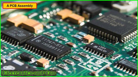
Metal core printed circuit boards (PCBs) have emerged as a significant advancement in the field of electronics, particularly when integrated with through-hole technology. This combination offers a multitude of advantages that enhance the performance and reliability of electronic devices. To begin with, metal core PCBs are renowned for their superior thermal management capabilities. The metal core, typically composed of aluminum or copper, acts as an excellent heat sink, efficiently dissipating heat away from critical components. This is particularly beneficial in through-hole technology, where components are mounted by inserting their leads into pre-drilled holes on the PCB. The enhanced thermal conductivity of metal core PCBs ensures that heat generated by these components is effectively managed, thereby reducing the risk of overheating and prolonging the lifespan of the device.
Moreover, the integration of metal core PCBs with through-hole technology offers improved mechanical stability.
Through-hole components are known for their robust mechanical connections, as the leads are soldered on both sides of the board. This results in a more durable assembly that can withstand mechanical stress and vibrations. When combined with the sturdy nature of metal core PCBs, the overall structural integrity of the electronic device is significantly enhanced. This makes metal core PCBs particularly suitable for applications in harsh environments, such as automotive and industrial sectors, where devices are often subjected to extreme conditions.
In addition to thermal and mechanical advantages, metal core PCBs in through-hole technology also contribute to improved electrical performance.
The metal core provides a low-impedance path for electrical signals, which minimizes signal distortion and enhances the overall performance of the circuit. This is especially important in high-frequency applications, where maintaining signal integrity is crucial. Furthermore, the use of through-hole technology allows for the incorporation of larger components, such as transformers and capacitors, which are essential for power management and signal conditioning in complex electronic systems.
Another noteworthy advantage is the ease of assembly and repair associated with through-hole technology on metal core PCBs.
The larger size of through-hole components and the visibility of their leads make them easier to handle during assembly. This is particularly advantageous in prototyping and small-scale production, where manual assembly is often required. Additionally, the robust nature of through-hole connections simplifies the repair process, as components can be easily desoldered and replaced without damaging the PCB. This ease of maintenance is a significant benefit in applications where reliability and longevity are paramount.
Furthermore, the combination of metal core PCBs and through-hole technology supports a wide range of applications, from consumer electronics to high-power industrial equipment.
The versatility of this integration allows designers to optimize their circuits for specific requirements, whether it be enhanced thermal management, mechanical stability, or electrical performance. As a result, metal core PCBs in through-hole technology are increasingly being adopted in various industries, driving innovation and improving the functionality of electronic devices.
In conclusion, the advantages of metal core PCBs in through-hole technology are manifold, encompassing superior thermal management, mechanical stability, electrical performance, ease of assembly, and versatility. These benefits make them an ideal choice for a wide array of applications, ensuring that electronic devices operate efficiently and reliably even in challenging conditions. As technology continues to evolve, the integration of metal core PCBs with through-hole technology is poised to play a pivotal role in advancing the capabilities of electronic systems.
Thermal Management In Metal Core PCB Through-Hole Applications
Metal core printed circuit boards (MCPCBs) have become increasingly significant in applications where efficient thermal management is crucial. These specialized PCBs are designed to dissipate heat more effectively than traditional fiberglass boards, making them ideal for high-power applications such as LED lighting, power supplies, and automotive systems. One of the key features of MCPCBs is their ability to incorporate through-hole components, which are essential for certain applications that require robust mechanical connections and reliable electrical performance. Understanding the role of through-hole technology in metal core PCBs is vital for optimizing thermal management and ensuring the longevity and reliability of electronic devices.
To begin with, the primary advantage of using metal core PCBs is their enhanced thermal conductivity.
The metal core, typically made of aluminum or copper, acts as a heat sink, drawing heat away from critical components and distributing it across the board. This is particularly beneficial in through-hole applications, where components such as capacitors, inductors, and connectors generate significant amounts of heat. By efficiently transferring heat away from these components, MCPCBs help prevent overheating, which can lead to component failure and reduced performance.
Moreover, through-hole technology in metal core PCBs offers superior mechanical stability compared to surface-mount technology (SMT).
Through-hole components are inserted into pre-drilled holes and soldered on the opposite side of the board, creating a strong mechanical bond. This is especially important in applications subject to mechanical stress or vibration, such as automotive or industrial environments. The robust connection provided by through-hole technology ensures that components remain securely attached to the board, reducing the risk of failure due to mechanical fatigue.
In addition to mechanical stability, through-hole technology also enhances electrical performance in metal core PCBs.
The direct connection between the component leads and the metal core allows for lower electrical resistance and improved current-carrying capacity. This is crucial in high-power applications where efficient power distribution is necessary to maintain optimal performance. Furthermore, the use of through-hole components can simplify the design and manufacturing process, as they are generally easier to handle and place than their surface-mount counterparts.
However, integrating through-hole components into metal core PCBs presents certain challenges that must be addressed to maximize thermal management.
One such challenge is the potential for thermal expansion mismatch between the metal core and the through-hole components. This can lead to stress on the solder joints, potentially causing them to crack or fail over time. To mitigate this risk, careful consideration must be given to the selection of materials and the design of the PCB layout. For instance, using thermal vias and strategically placing components can help distribute heat more evenly and reduce thermal stress.
Furthermore, the drilling process for through-hole components in metal core PCBs requires precision and expertise.
The metal core must be drilled accurately to ensure proper alignment and fit of the components, while also maintaining the integrity of the thermal path. Advanced manufacturing techniques, such as laser drilling, can be employed to achieve the necessary precision and quality.
In conclusion, the integration of through-hole technology in metal core PCBs plays a crucial role in enhancing thermal management for high-power applications. By leveraging the superior thermal conductivity, mechanical stability, and electrical performance of MCPCBs, designers can create reliable and efficient electronic devices. However, careful consideration of material selection, PCB layout, and manufacturing processes is essential to overcome the challenges associated with through-hole technology in metal core PCBs. As technology continues to advance, the demand for effective thermal management solutions will only increase, making the role of metal core PCBs in through-hole applications more important than ever.
Design Considerations For Metal Core PCB With Through-Hole Components
When designing metal core printed circuit boards (MCPCBs) with through-hole components, several critical considerations must be taken into account to ensure optimal performance and reliability. Metal core PCBs are renowned for their superior thermal management capabilities, making them ideal for applications where heat dissipation is crucial. However, integrating through-hole components into these boards introduces unique challenges that require careful planning and execution.
To begin with, the choice of materials is paramount.
The core material, typically aluminum or copper, plays a significant role in the board’s thermal conductivity. Aluminum is often preferred due to its balance of cost-effectiveness and thermal performance, while copper offers superior thermal conductivity but at a higher cost. The selection of the core material should align with the thermal requirements of the application and the budget constraints of the project.
Moreover, the thickness of the metal core is another vital factor.
A thicker core can enhance heat dissipation but may also increase the overall weight and cost of the PCB. Therefore, designers must strike a balance between thermal performance and other design constraints. Additionally, the dielectric layer, which electrically insulates the metal core from the circuit, must be carefully chosen to ensure it can withstand the thermal and electrical demands of the application.
Transitioning to the layout of through-hole components, it is essential to consider the thermal expansion properties of the materials involved.
The coefficient of thermal expansion (CTE) of the metal core, dielectric layer, and through-hole components should be compatible to minimize stress and potential damage during thermal cycling. Mismatched CTEs can lead to mechanical failures, such as cracking or delamination, which can compromise the integrity of the PCB.
Furthermore, the placement of through-hole components requires meticulous attention.
Components that generate significant heat should be strategically positioned to maximize heat dissipation through the metal core. This often involves placing high-power components closer to the core and ensuring adequate thermal pathways are established. Additionally, the use of thermal vias can further enhance heat transfer from the components to the metal core, thereby improving the overall thermal management of the PCB.
In addition to thermal considerations, electrical performance must not be overlooked.
The design should ensure minimal signal loss and interference, which can be achieved by optimizing the trace layout and maintaining appropriate spacing between components. The use of ground planes and shielding techniques can also help mitigate electromagnetic interference, thereby enhancing the board’s electrical performance.
As the design progresses, manufacturability should remain a key focus.
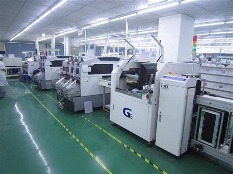
The integration of through-hole components into metal core PCBs can complicate the manufacturing process, necessitating specialized techniques such as selective soldering or wave soldering. Collaborating closely with manufacturers during the design phase can help identify potential challenges and develop solutions that streamline production while maintaining quality.
Finally, testing and validation are crucial steps in the design process.
Prototyping and rigorous testing can identify potential issues early, allowing for adjustments before full-scale production. Thermal analysis, electrical testing, and mechanical stress testing are essential to ensure the PCB meets all performance and reliability requirements.
In conclusion, designing metal core PCBs with through-hole components involves a complex interplay of material selection, thermal management, electrical performance, and manufacturability. By carefully considering each of these aspects and employing a holistic design approach, engineers can create robust and efficient PCBs that meet the demanding requirements of modern electronic applications.
Comparing Metal Core PCB Through-Hole And Surface Mount Technologies
In the realm of printed circuit board (PCB) design and manufacturing, the choice between through-hole technology (THT) and surface mount technology (SMT) is pivotal, particularly when dealing with metal core PCBs (MCPCBs). These specialized PCBs, known for their superior heat dissipation capabilities, are increasingly utilized in high-power applications such as LED lighting, power converters, and automotive electronics. Understanding the nuances of through-hole and surface mount technologies in the context of MCPCBs is essential for engineers and designers aiming to optimize performance and reliability.
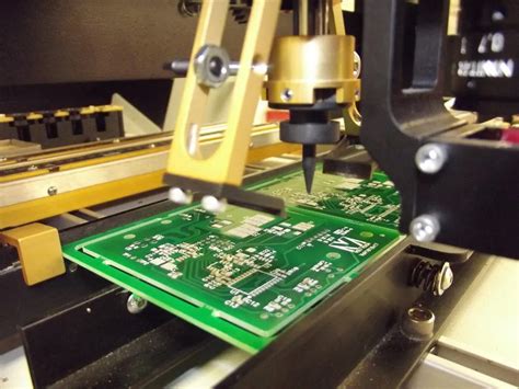
Through-hole technology, a traditional method of mounting components, involves inserting component leads through pre-drilled holes on the PCB and soldering them on the opposite side.
This technique offers several advantages, especially in terms of mechanical strength. Components mounted using THT are securely fastened, making them ideal for applications subject to mechanical stress or vibration. Moreover, through-hole components are generally easier to replace or repair, which can be a significant advantage in prototyping and testing phases.
However, when applied to metal core PCBs, through-hole technology presents certain challenges.
The drilling process can be more complex and costly due to the metal core, which requires specialized equipment and techniques. Additionally, the thermal conductivity of the metal core can complicate the soldering process, as heat dissipation may affect solder joint formation. Despite these challenges, through-hole technology remains a viable option for MCPCBs in applications where mechanical stability and ease of repair are prioritized.
In contrast, surface mount technology, which involves mounting components directly onto the surface of the PCB, offers distinct advantages in terms of design flexibility and manufacturing efficiency.
SMT allows for higher component density, enabling more compact and lightweight designs. This is particularly beneficial in applications where space is at a premium. Furthermore, the automated nature of SMT assembly processes can lead to reduced production costs and time, making it an attractive option for high-volume manufacturing.
When applied to metal core PCBs, surface mount technology can enhance thermal management capabilities.
The direct contact between components and the metal core facilitates efficient heat transfer, which is crucial in high-power applications. However, SMT also presents its own set of challenges. The soldering process requires precise temperature control to ensure reliable connections, as the metal core’s thermal properties can lead to rapid heat dissipation. Additionally, the repair and replacement of surface-mounted components can be more complex compared to through-hole components, potentially increasing maintenance costs.
In comparing these two technologies, it is evident that the choice between through-hole and surface mount for metal core PCBs depends largely on the specific requirements of the application.
Through-hole technology may be preferable in scenarios where mechanical robustness and ease of repair are critical, while surface mount technology may be more suitable for applications demanding compactness and efficient thermal management. Ultimately, the decision should be guided by a thorough analysis of the application’s performance, reliability, and cost considerations.
In conclusion, both through-hole and surface mount technologies offer unique advantages and challenges when applied to metal core PCBs. By carefully evaluating the specific needs of their applications, engineers and designers can make informed decisions that leverage the strengths of each technology, thereby optimizing the performance and reliability of their electronic products.


