Metal Core Printed Circuit Boards (MCPCB): Design, Applications, and Advantages
Introduction to MCPCB Technology
Metal Core Printed Circuit Boards (MCPCBs), also known as thermal PCBs or insulated metal substrates (IMS), represent a significant advancement in printed circuit board technology designed to address the critical challenge of thermal management in modern electronics. Unlike traditional FR4 PCBs that use a fiberglass substrate, MCPCBs incorporate a metal base—typically aluminum or copper—as their foundational layer, providing superior heat dissipation capabilities.
The concept of metal-backed circuit boards emerged in the 1960s but gained substantial commercial importance in the 1990s with the rapid development of high-power LED lighting and power electronics. Today, MCPCBs have become indispensable components in applications where efficient heat transfer is paramount to maintaining device reliability and performance.
Structure and Composition of MCPCBs
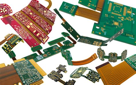
The architecture of a metal core PCB differs significantly from conventional circuit boards through its layered construction:
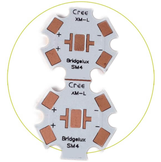
- Base Metal Layer: This forms the thickest part of the board (typically 1mm-3mm) and serves as the primary heat spreader. Aluminum is most common (about 90% of MCPCBs) due to its favorable balance of thermal conductivity, weight, and cost. Copper offers even better thermal performance (about twice that of aluminum) but at higher cost and weight.
- Dielectric Layer: A thin thermally conductive but electrically insulating layer (usually 50μm-150μm) bonds the circuit layer to the metal base. This layer must withstand high voltages while efficiently transferring heat. Modern dielectric materials achieve thermal conductivities of 1-3 W/mK, compared to just 0.3 W/mK for standard FR4.
- Circuit Layer: A copper foil (typically 1oz-4oz) etched to form the conductive traces. Some high-power applications use thicker copper up to 12oz (420μm).
- Solder Mask: Applied over the circuit layer for protection and to define solder areas. White solder mask is particularly common for LED applications to enhance light reflection.
- Surface Finish: Options include HASL (Hot Air Solder Leveling), ENIG (Electroless Nickel Immersion Gold), or OSP (Organic Solderability Preservative) depending on component requirements.
Thermal Management Properties
The thermal performance of MCPCBs is quantified by several key parameters:
- Thermal Conductivity: Aluminum MCPCBs typically achieve 1-3 W/mK through the entire stackup, compared to just 0.3 W/mK for FR4. Copper-based boards can reach up to 5 W/mK.
- Thermal Resistance: Measured in °C/W, this indicates how effectively heat transfers from components to the environment. A well-designed MCPCB might have junction-to-case thermal resistance as low as 1-5°C/W.
- CTE (Coefficient of Thermal Expansion) Matching: The 26 ppm/°C CTE of aluminum closely matches that of ceramic chip packages (6-8 ppm/°C) and silicon (4 ppm/°C), reducing thermal stress compared to FR4 (14-18 ppm/°C).
Heat dissipation occurs through three primary mechanisms in MCPCBs:
- Conduction: Heat spreads rapidly through the metal core
- Convection: The large metal surface area transfers heat to air
- Radiation: Especially effective with black anodized surfaces
Advanced thermal simulation using tools like ANSYS or FloTHERM is often employed to optimize MCPCB layouts for maximum heat dissipation.
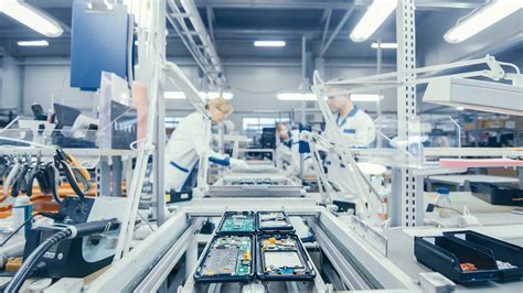
Manufacturing Process
The production of metal core PCBs involves specialized processes:
- Metal Base Preparation: Aluminum cores are typically anodized to prevent oxidation. Copper cores may require additional plating.
- Dielectric Layer Application: The thermally conductive dielectric is either laminated as a prepreg or applied as a thermally conductive adhesive (TCA). Laser drilling may create vias.
- Circuit Patterning: Standard photolithography processes etch the copper layer, though thicker copper may require specialized etching.
- Machining: MCPCBs often require routing, drilling, and punching. Diamond-coated tools are necessary for aluminum substrates.
- Testing: Includes thermal cycling tests, high-potential (hipot) tests for dielectric integrity, and thermal imaging analysis.
Key manufacturing challenges include:
- Achieving uniform dielectric thickness
- Preventing metal core deformation during processing
- Managing different CTEs between materials
- Ensuring reliable plating of through-holes in thicker boards
Design Considerations for MCPCBs
Effective MCPCB design requires attention to several unique factors:
Thermal Design
- Component placement to avoid hot spots
- Thermal relief patterns for soldering
- Optimal copper thickness for current and heat
- Consideration of external heatsinking needs
Electrical Design
- Dielectric layer thickness vs. voltage requirements
- Trace width calculations accounting for both current and thermal effects
- High-frequency signal integrity considerations
Mechanical Design
- Board thickness selection based on thermal and mechanical needs
- Mounting hole placement to avoid stress
- Edge clearance requirements
Special Features
- Thermal vias for enhanced heat transfer
- Castellated holes for edge connections
- Selective copper thickening in high-current areas
Design software like Altium Designer and Cadence Allegro now include specific MCPCB design rules and thermal simulation plugins to assist engineers.
Applications of MCPCB Technology
The unique properties of metal core PCBs make them ideal for numerous applications:
LED Lighting (70% of MCPCB market)
- High-power LED arrays
- Street lighting
- Automotive lighting (headlights, DRLs)
- Stage and architectural lighting
Power Electronics
- Motor drives
- Power converters
- UPS systems
- Solar inverters
Automotive
- Electric vehicle power systems
- Battery management
- LED headlights and taillights
Industrial Equipment
- Welding controls
- Industrial lasers
- Power supplies
Consumer Electronics
- High-end audio amplifiers
- Gaming console power systems
- High-power RF devices
Emerging applications include 5G infrastructure, high-performance computing, and aerospace systems where thermal management is critical.
Advantages and Limitations
Key Advantages:
- Thermal Performance: Can reduce junction temperatures by 30-50°C compared to FR4
- Longer Component Life: Every 10°C reduction doubles semiconductor lifespan
- Space Savings: Eliminates separate heatsinks in many applications
- Weight Reduction: Aluminum MCPCBs are lighter than copper heatsink solutions
- Improved Reliability: Better CTE matching reduces solder joint fatigue
- Simplified Assembly: Fewer thermal interface materials required
Limitations and Challenges:
- Higher Cost: Typically 2-4x the cost of equivalent FR4 boards
- Layer Limitations: Most are single or double-layer; multilayer complex
- Via Challenges: Through-hole vias require special processing
- Design Constraints: Larger minimum trace widths/spacing
- Component Restrictions: Some SMT components may not suit metal-backed boards
Comparison with Alternative Technologies
MCPCB vs. Standard FR4:
- FR4 is adequate for <1W/cm² power density
- MCPCB required for 1-5W/cm²
- For >5W/cm², active cooling still needed
MCPCB vs. Ceramic Substrates:
- Ceramics (AlN, BeO) offer better thermal performance (170-200 W/mK)
- But ceramics are brittle and expensive
- MCPCBs provide better mechanical robustness
MCPCB vs. Direct Bonded Copper (DBC):
- DBC has superior thermal performance
- But limited size availability and higher cost
- MCPCBs offer more design flexibility
Future Trends in MCPCB Technology
The MCPCB market is projected to grow at 8-10% CAGR through 2028, driven by:
- Advanced Dielectrics: Development of polymer-ceramic composites with thermal conductivities >5 W/mK
- Embedded Components: Direct chip attachment to metal cores for highest thermal performance
- Additive Manufacturing: 3D printed metal substrates with optimized thermal paths
- Hybrid Structures: Combining MCPCB with traditional multilayer sections
- Standardization: IPC standards specifically for metal-clad PCBs
- Sustainability: Recyclable aluminum cores and lead-free processes
Research areas include nano-enhanced thermal interface materials and advanced metal alloys with tailored CTE properties.
Conclusion
Metal Core PCB technology has established itself as a critical solution for thermal management challenges in modern electronics. By combining efficient heat dissipation with reliable electrical performance, MCPCBs enable higher power densities, greater reliability, and more compact designs across numerous industries. While the technology carries some cost premium and design limitations compared to conventional PCBs, its benefits in thermal-critical applications are undeniable.
As electronic devices continue to push power density limits and thermal management becomes increasingly challenging, MCPCB technology will likely see expanded adoption and continued innovation. Engineers must carefully evaluate thermal requirements early in the design process to determine when metal core solutions offer the optimal balance of performance, reliability, and cost.
The future of MCPCBs appears bright, with advancements in materials science and manufacturing processes promising even better thermal performance and broader application possibilities in power electronics, advanced lighting, electric vehicles, and beyond.