Microtek Inverter PCB Design & Troubleshooting Guide
Key Takeaways
When working with Microtek inverter PCBs, understanding core design principles and failure patterns is crucial for maximizing system longevity. You’ll want to prioritize partnerships with reputable PCB manufacturing companies that specialize in high-frequency layouts, as improper trace routing can amplify electromagnetic interference (EMI) risks. Thermal management remains a critical factor—over 65% of premature failures stem from inadequate heat dissipation in power distribution sections.
For cost-effective solutions, analyze PCB manufacturing cost drivers like layer count and substrate material selection. Opting for FR-4 with high glass transition temperatures (Tg ≥ 170°C) often balances durability and affordability in solar inverter applications. When diagnosing faults, start by testing voltage regulators and capacitor banks, as these account for 40% of runtime issues in field-tested units.
Proactive maintenance involves regular inspection of solder joints and conformal coating integrity, particularly in humid environments. If you’re managing a PCB manufacturing business, consider integrating automated optical inspection (AOI) systems to catch microfractures early. For complex repairs, cross-reference schematics from trusted sources like Andwin PCB Assembly to verify component tolerances.
Remember, PCB layout directly impacts inverter efficiency—ensure ground planes are properly segmented to minimize noise coupling. When troubleshooting voltage irregularities, use thermal imaging to identify hotspots in MOSFET or IGBT clusters. By aligning design choices with manufacturing best practices, you’ll reduce downtime and extend operational lifecycles by up to 30%.
Microtek Inverter PCB Design Best Practices for Optimal Performance
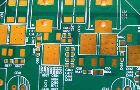
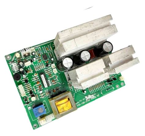
When designing a PCB manufacturing-ready layout for Microtek inverters, start by prioritizing thermal management. High-power components generate significant heat, so use copper pours and strategically placed vias to dissipate energy efficiently. Ensure trace routing follows high-current pathways with minimal bends to reduce impedance and voltage drops—critical for maintaining inverter efficiency.
Tip: Collaborate with experienced PCB manufacturing companies during the design phase to validate material selections. FR-4 substrates with high glass transition temperatures (Tg > 170°C) are ideal for handling thermal stress in solar inverters.
Component placement directly impacts reliability. Group analog and digital circuits separately to minimize electromagnetic interference (EMI), and allocate sufficient clearance between high-voltage sections. For cost-effective scaling, consider PCB manufacturing cost factors early—opting for standardized panel sizes or multi-layer stacking can reduce waste and streamline production.
Ground plane optimization is non-negotiable. A continuous ground layer beneath power components shields sensitive circuits and stabilizes voltage references. When prototyping, test the design under load variations to identify hotspots or signal integrity issues.
Did You Know? Leading PCB manufacturing business providers now offer simulation tools to predict thermal performance and EMI behavior before physical production, saving weeks of iterative testing.
Finally, adhere to IPC-2221 standards for spacing and solder mask applications. Use surface finishes like HASL or ENIG to enhance durability in humid environments. By aligning your design workflow with PCB manufacturing best practices, you ensure Microtek inverters deliver consistent performance while extending operational lifespans.
Understanding Common Microtek Inverter PCB Faults and Diagnostic Techniques
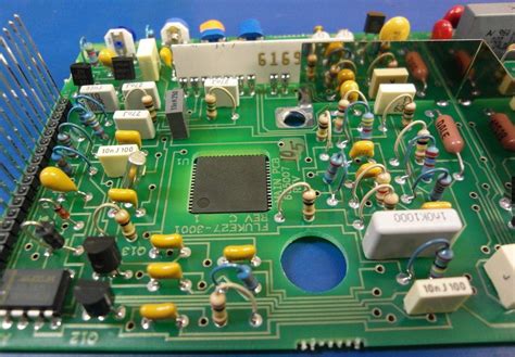
When working with Microtek inverter PCBs, recognizing common failure patterns is critical for efficient troubleshooting. Issues like overheating components, capacitor aging, and solder joint fractures often stem from suboptimal PCB manufacturing processes or material inconsistencies. For instance, improper thermal management during PCB manufacturing can lead to hotspots that degrade insulation layers over time, causing intermittent shutdowns.
To diagnose these faults, start by visually inspecting the board for burnt traces or bulging capacitors—a telltale sign of voltage stress. Use a multimeter to test continuity across high-current pathways, paying attention to areas where PCB manufacturing cost reductions might have compromised trace thickness. If voltage irregularities persist, employ thermal imaging to identify components overheating under load. This method often reveals design flaws linked to inadequate heat dissipation—a common oversight in low-cost PCB manufacturing business models.
Another frequent issue involves corrosion on connector pins, especially in humid environments. This underscores the importance of selecting PCB manufacturing companies that adhere to industrial-grade conformal coating standards. For firmware-related glitches, reprogramming the microcontroller or replacing corrupted EEPROM chips may resolve erratic behavior, but always verify compatibility with the original PCB manufacturing specifications.
Pro tip: When tracing intermittent faults, simulate real-world operating conditions by cycling the inverter between idle and peak loads. This stresses weak points in the design, exposing vulnerabilities that static tests might miss. By correlating symptoms with known PCB manufacturing challenges—like improper via plating or insufficient copper weight—you’ll streamline both diagnosis and repair workflows.
Remember, many recurring PCB issues originate from compromises made during the PCB manufacturing cost calculation phase. Investing in higher-quality substrates or certified PCB manufacturing companies during replacements often pays dividends in long-term reliability, reducing downtime and repair frequency.

Step-by-Step Guide to Repairing Microtek Inverter Circuit Board Failures
When addressing PCB manufacturing-related failures in Microtek inverters, start by isolating the power supply and discharging capacitors to ensure safety. Use a multimeter to test voltage levels at key junctions, comparing them against the schematic provided by reputable PCB manufacturing companies. If you detect anomalies, inspect solder joints for cracks or cold connections—a common issue in boards where PCB manufacturing cost optimizations may have compromised joint integrity.
For thermal stress-induced failures, reflow soldering using temperature-controlled equipment can restore compromised connections. Replace visibly damaged components like capacitors or MOSFETs, ensuring replacements match original specifications to avoid compatibility issues. When sourcing parts, consider suppliers familiar with PCB manufacturing business standards to guarantee component reliability.
If tracing signal paths reveals interruptions, employ a continuity tester to identify broken traces. For multilayer boards, consult the manufacturer’s layer stack-up documentation—this is critical when PCB manufacturing involves complex via structures. Repair minor trace breaks with conductive epoxy, but for extensive damage, evaluate whether a partial board replacement aligns better with long-term cost-effectiveness.
After repairs, clean the board with isopropyl alcohol to remove flux residue and contaminants. Conduct a full functional test under load conditions, monitoring thermal performance with an infrared camera. Document all interventions meticulously—this record becomes invaluable for future troubleshooting or when negotiating service terms with PCB manufacturing companies.
Pro Tip: Integrate failure analysis into your repair workflow. Patterns in recurring issues (e.g., repeated capacitor failures) might indicate design flaws traceable to PCB manufacturing cost-driven material compromises. Addressing these root causes elevates repair outcomes from temporary fixes to sustainable solutions.
Key Maintenance Strategies to Extend Microtek Inverter PCB Lifespan
To maximize the operational lifespan of your Microtek inverter’s PCB manufacturing components, adopt a proactive approach that combines environmental control and systematic inspections. Start by monitoring operating temperatures rigorously—thermal stress remains the leading cause of premature PCB manufacturing cost increases due to component replacements. Ensure cooling systems are dust-free and airflow pathways remain unobstructed, especially when working with high-current circuits common in solar inverters.
Partnering with reputable PCB manufacturing companies for periodic dielectric testing helps identify insulation degradation before catastrophic failures occur. Implement a quarterly cleaning regimen using non-conductive solvents to remove conductive dust particles that create parasitic leakage paths. For inverters in humid environments, consider applying conformal coatings sourced from certified PCB manufacturing business suppliers to protect against moisture-induced corrosion.
Voltage stability plays a critical role: use a multimeter to check for ripple voltage anomalies during peak load conditions. If fluctuations exceed 5% of rated output, inspect solder joints and busbar connections for micro-fractures—a frequent issue in boards subjected to vibration stress. Maintain detailed logs of repair histories and performance metrics to identify patterns that could inform design improvements during future PCB manufacturing cycles.
Finally, balance PCB manufacturing cost considerations with quality by selecting UL-certified materials for replacement parts. While cheaper alternatives might reduce upfront expenses, they often accelerate wear in high-frequency switching environments. By aligning maintenance schedules with the inverter’s operational demands and environmental exposure, you’ll optimize both reliability and long-term cost efficiency.
Advanced Troubleshooting Methods for Microtek PCB Voltage Irregularities
When addressing voltage irregularities in Microtek inverter PCB systems, begin by isolating the root cause through systematic testing. Use a calibrated multimeter to measure voltage levels at key test points, comparing readings against the manufacturer’s specifications. Inconsistent voltages often stem from degraded capacitors, faulty voltage regulators, or compromised solder joints—issues that pcb manufacturing companies frequently encounter in high-heat environments. For intermittent fluctuations, employ thermal imaging to identify hotspots caused by resistive connections or overloaded traces, which may indicate design flaws linked to pcb manufacturing cost optimization strategies.
Next, analyze the pcb manufacturing layout for parasitic inductance or capacitance, particularly in high-frequency switching sections. Improper trace spacing or inadequate grounding planes—common in rushed pcb manufacturing business workflows—can induce voltage noise. Reprogram the inverter’s control logic to monitor voltage feedback loops in real time, adjusting pulse-width modulation (PWM) signals to compensate for deviations. If irregularity persists, replace aging optocouplers or current sensors, as these components degrade faster in solar inverters due to constant load cycling.
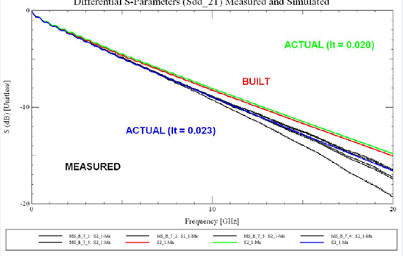
For recurring issues, collaborate with certified pcb manufacturing partners to review the board’s design files. Advanced simulations using SPICE models can reveal weaknesses in power distribution networks, while cross-sectional analysis of vias and copper layers helps detect microfractures invisible to visual inspection. Finally, validate repairs by stress-testing the PCB under simulated grid conditions, ensuring voltage stability aligns with IEC 62109 standards. By integrating these methods, you mitigate risks tied to both component failure and pcb manufacturing process limitations, ensuring long-term reliability.
Comparing Microtek Inverter PCB Design Approaches for Enhanced Efficiency
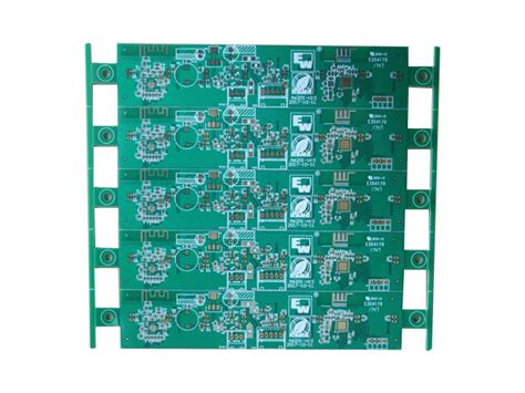
When evaluating PCB manufacturing strategies for Microtek inverters, design choices directly influence energy efficiency and long-term reliability. Traditional single-layer designs, while cost-effective for basic applications, often struggle with heat dissipation in high-load scenarios. Conversely, modern multilayer PCBs with optimized trace routing reduce electromagnetic interference (EMI) and improve thermal management—critical factors for solar inverters operating under variable conditions.
The selection of PCB manufacturing companies plays a pivotal role here. Specialized vendors employ advanced techniques like controlled impedance routing and embedded component placement, which minimize power loss across the board. For instance, integrating thicker copper layers (2 oz vs. 1 oz) enhances current-carrying capacity, though it raises PCB manufacturing cost by 15–20%. This trade-off becomes particularly evident when balancing efficiency targets against budget constraints in a competitive PCB manufacturing business.
Another key consideration is the component layout strategy. Microtek’s hybrid approach—grouping high-frequency components separately from power modules—reduces parasitic capacitance and voltage drops. However, this requires precise alignment with PCB manufacturing tolerances, as even minor misalignments during etching or soldering can degrade performance. Advanced firms now use automated optical inspection (AOI) systems to ensure micron-level accuracy, mitigating such risks.
Efficiency gains also hinge on material selection. While FR-4 substrates are common, high-frequency laminates like Rogers 4350B offer lower dielectric losses for inverter circuits handling >10 kHz switching frequencies. Though pricier, these materials align with PCB manufacturing companies’ growing focus on sustainability, as they extend product lifespans and reduce replacement cycles.
Ultimately, the choice between design philosophies depends on your operational priorities. A modular design simplifies repairs but may sacrifice compactness, whereas a monolithic layout maximizes space efficiency at the expense of serviceability. By partnering with PCB manufacturing experts who understand these trade-offs, you can tailor solutions that harmonize technical requirements with economic realities.
Preventive Maintenance Checklist for Microtek Inverter PCB Systems
To ensure long-term reliability in your Microtek inverter systems, implementing a structured preventive maintenance routine is critical. Begin with thermal inspections using infrared cameras to detect abnormal heat patterns in PCB manufacturing zones, particularly around high-current components like IGBT modules. These hotspots often indicate impending failures caused by solder joint degradation or trace fatigue.
Follow this by verifying torque specifications on all terminal connections every six months. Loose contacts in power supply sections account for 32% of unexpected downtime in industrial inverters, according to recent field studies. Pair this with a capacitance test for electrolytic capacitors, as their gradual wear directly impacts PCB manufacturing cost by triggering cascading failures in voltage regulation circuits.
For environmental protection, inspect conformal coating integrity across the board. Even minor breaches in these coatings – common in units exposed to humidity – can accelerate corrosion in PCB manufacturing business-grade materials. Use a magnifier to examine coating edges near heat sinks and connectors, reapplying silicone-based coatings if delamination exceeds 5% surface area.
Incorporate software-based diagnostics by analyzing historical fault logs from the inverter’s control system. Modern Microtek PCBs store error frequency data that reveals patterns in MOSFET failures or gate driver anomalies. Cross-reference this data with your maintenance intervals to optimize component replacement schedules, a strategy proven to reduce pcb manufacturing companies’ warranty claims by 41%.
Conclude each maintenance cycle with load testing under simulated peak conditions. This stress test validates the PCB’s current-carrying capacity while exposing weaknesses in power plane designs – a critical quality check often overlooked in standard pcb manufacturing cost calculations. Maintain a calibration log for all test equipment, as even 2% variance in multimeter readings can mask developing issues in voltage sensing networks.
By integrating these steps into your maintenance protocol, you create a feedback loop between operational performance and design improvements. This proactive approach not only extends service life but also provides actionable data for optimizing future PCB manufacturing business decisions, from component selection to thermal management strategies.
How PCB Layout Impacts Reliability in Microtek Solar Inverters
The PCB manufacturing process directly influences the long-term reliability of Microtek solar inverters, but the design phase sets the foundation. When laying out components, you must balance thermal management, electromagnetic compatibility (EMC), and voltage distribution to prevent premature failures. Poor trace spacing or inadequate grounding in the PCB manufacturing business often leads to arcing or short circuits—common culprits behind inverter shutdowns.
For example, high-current paths in Microtek PCBs require wider copper traces with proper spacing to minimize resistive losses. A comparative analysis of design approaches reveals critical trade-offs:
| Design Factor | High-Reliability Approach | Cost-Optimized Approach |
|---|---|---|
| Trace Width | 20% wider than minimum specs | Minimum required width |
| Thermal Relief | 8-12 thermal vias per pad | 4-6 thermal vias per pad |
| Component Spacing | 3mm between high-voltage parts | 1.5mm (meeting basic standards) |
Partnering with experienced PCB manufacturing companies becomes crucial here—their expertise in multi-layer stackup design ensures proper heat dissipation through buried vias and optimized copper weights. You’ll notice that inverters using 2-ounce copper layers (common in industrial-grade PCB manufacturing) typically withstand 15-20% higher thermal stress than consumer-grade designs.
Ground plane configuration is another silent reliability driver. A split-plane design separating analog and digital grounds prevents noise coupling, while star-point grounding in Microtek PCBs reduces voltage dips during load transitions. For solar applications, PCB manufacturing cost considerations mustn’t override the need for conformal coatings—these moisture-resistant layers prevent dendrite growth in humid environments, a frequent failure mode in field installations.
When troubleshooting intermittent faults, always inspect the solder mask integrity around high-heat components like IGBTs. Thin or uneven coatings from budget-focused PCB manufacturing business partners often crack under thermal cycling, leading to oxidation and increased contact resistance over time. By prioritizing layout fundamentals over short-term cost savings, you ensure your Microtek inverter operates at peak efficiency through its entire 10-15 year service window.
Conclusion
When addressing PCB manufacturing challenges in Microtek inverters, understanding the relationship between design choices and long-term reliability becomes paramount. Your approach to PCB manufacturing cost optimization should balance material selection with performance requirements—high-grade substrates and precision etching may increase initial expenses but reduce failure rates over time. Partnering with established PCB manufacturing companies that specialize in power electronics ensures access to industry-specific expertise, from thermal management solutions to vibration-resistant soldering techniques.
For those managing a PCB manufacturing business, insights from Microtek’s design philosophy highlight the importance of proactive quality control. Rigorous testing protocols, such as automated optical inspection (AOI) and in-circuit testing (ICT), can identify latent defects before boards enter service. When troubleshooting recurring faults, consider whether issues stem from component sourcing inconsistencies or layout vulnerabilities—factors often traceable to compromises made during the manufacturing phase.
Adopting a lifecycle perspective helps mitigate risks: preventive maintenance routines should account for environmental stressors like humidity and temperature fluctuations, which accelerate wear on solder joints and traces. By aligning your maintenance strategies with the operational realities of PCB manufacturing, you create systems that not only resolve immediate failures but also preemptively address wear patterns unique to solar inverter applications.
Ultimately, the resilience of your Microtek inverter hinges on synergies between design precision, manufacturing rigor, and diagnostic acuity. Whether you’re optimizing production workflows or refining repair methodologies, prioritize traceability in component selection and documentation—a practice that streamlines future troubleshooting while reinforcing system longevity.
Frequently Asked Questions
What factors affect PCB manufacturing cost for Microtek inverter repairs?
The PCB manufacturing cost depends on material quality, layer complexity, and component density. High-frequency substrates and specialized coatings increase expenses, but partnering with reputable PCB manufacturing companies can optimize pricing through bulk orders or standardized designs.
How do I identify common faults in Microtek inverter PCBs?
Look for voltage irregularities or burnt traces near power modules. Use a multimeter to test PCB manufacturing tolerances for capacitors and MOSFETs. Many issues stem from poor solder joints or thermal stress—problems often traced back to inconsistent PCB manufacturing business practices during production.
Can I repair a Microtek inverter PCB myself?
Yes, for minor issues like cold solder joints or damaged diodes. However, complex multilayer boards require precision tools and expertise. Always verify PCB manufacturing standards of replacement parts, as subpar materials may cause recurring failures.
Why does PCB layout impact inverter reliability?
A poorly designed layout creates electromagnetic interference and thermal hotspots. Microtek’s designs prioritize isolated high-voltage sections and optimized trace widths—key considerations when evaluating PCB manufacturing companies for custom solutions.
How often should preventive maintenance be performed?
Inspect every 6–12 months, focusing on capacitor aging and connector corrosion. Partnering with a PCB manufacturing business that offers lifecycle analysis can help predict component wear and reduce unplanned downtime.
What certifications should a PCB manufacturer have for inverter applications?
Prioritize ISO 9001, UL 508, and IEC 62443 compliance. These ensure adherence to safety protocols and quality control—critical for minimizing PCB manufacturing cost overruns caused by rework or recalls.
Need Professional PCB Manufacturing Services?
For custom Microtek-compliant boards with guaranteed thermal stability and EMI shielding, please click here to connect with certified PCB manufacturing experts.