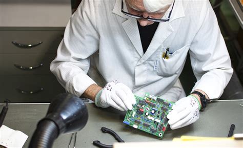
Military-Grade PCBs: Design, Materials, and Manufacturing Considerations
Introduction
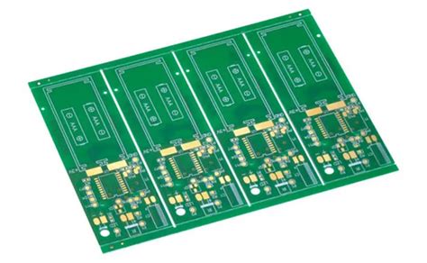
Printed Circuit Boards (PCBs) are fundamental components in modern electronics, serving as the backbone for nearly all electronic devices. While commercial-grade PCBs are sufficient for everyday applications, military-grade PCBs must meet stringent requirements to ensure reliability, durability, and performance in extreme environments. Military applications demand PCBs that can withstand harsh conditions, including high temperatures, mechanical stress, radiation, and electromagnetic interference (EMI).
This article explores the key aspects of military-grade PCBs, including design considerations, material selection, manufacturing processes, and testing standards. Understanding these factors is crucial for engineers and manufacturers working on defense and aerospace applications.
1. Key Requirements for Military-Grade PCBs
Military and aerospace applications impose unique challenges that commercial PCBs cannot meet. Some of the critical requirements include:
1.1 High Reliability and Longevity
Military systems often operate in mission-critical scenarios where failure is not an option. PCBs must function flawlessly for extended periods, sometimes decades, without degradation.
1.2 Extreme Environmental Resistance
Military electronics may be exposed to:
- Wide temperature ranges (–55°C to +125°C or higher)
- High humidity and salt spray (for naval applications)
- Vibration and mechanical shock (e.g., in missiles or armored vehicles)
- Radiation (for space applications)
1.3 EMI/RFI Shielding
Military systems must resist electromagnetic interference (EMI) and radio frequency interference (RFI) to prevent signal degradation or data corruption.
1.4 High-Frequency Performance
Radar, communication systems, and electronic warfare (EW) applications require PCBs with excellent signal integrity at high frequencies (RF/microwave PCBs).
1.5 Compliance with Military Standards
Military PCBs must adhere to strict standards such as:
- MIL-PRF-31032 (Performance Specification for PCBs)
- MIL-PRF-55110 (Qualification Requirements for Rigid PCBs)
- IPC-6012 Class 3 (High-Reliability PCBs)
- MIL-STD-810 (Environmental Engineering Considerations)
2. Material Selection for Military PCBs
The choice of materials significantly impacts the performance and durability of military-grade PCBs. Key considerations include:
2.1 Substrate Materials
- FR-4 (Flame Retardant-4): Standard for commercial PCBs but often insufficient for military use.
- High-Tg FR-4: Glass transition temperature (Tg) above 170°C for better thermal stability.
- Polyimide: Excellent thermal resistance (up to 260°C), flexibility, and radiation hardness.
- PTFE (Teflon): Used in high-frequency applications due to low dielectric loss.
- Ceramic-based substrates: For extreme thermal and mechanical stress conditions.
2.2 Copper Foil
- Electrodeposited (ED) copper: Standard for most PCBs.
- Rolled annealed copper: Better for high-frequency applications due to smoother surfaces.
2.3 Conformal Coatings
To protect against moisture, dust, and chemicals:
- Acrylic – Easy to apply and remove.
- Silicone – Excellent thermal and moisture resistance.
- Parylene – Ultra-thin, pinhole-free coating for critical applications.

3. Design Considerations for Military PCBs
3.1 High-Density Interconnect (HDI) Technology
Military electronics often require compact designs with multiple layers (up to 30+ layers in some cases). HDI techniques such as microvias, blind/buried vias, and fine-pitch traces are essential.
3.2 Thermal Management
- Thermal vias to dissipate heat.
- Metal-core PCBs (MCPCBs) for high-power applications.
- Heat sinks and thermal pads for additional cooling.
3.3 Signal Integrity and Controlled Impedance
- Careful trace routing to minimize crosstalk.
- Impedance matching for high-speed digital and RF circuits.
3.4 Redundancy and Fault Tolerance
- Redundant circuits to ensure continued operation if a component fails.
- Self-healing materials (emerging technology).
4. Manufacturing and Testing
4.1 Rigid Quality Control
Military PCB manufacturing follows strict processes, including:
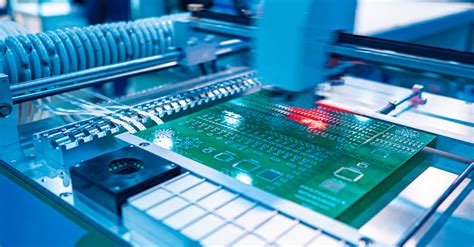
- Automated Optical Inspection (AOI) for detecting defects.
- X-ray inspection for checking internal layers and vias.
- Electrical testing (flying probe or bed-of-nails testing).
4.2 Environmental Stress Testing
- Thermal cycling (–65°C to +150°C).
- Vibration and shock testing (MIL-STD-810).
- Salt spray testing (for naval applications).
4.3 Certification and Traceability
- Full documentation of materials, processes, and test results.
- MIL-SPEC certification before deployment.

5. Applications of Military-Grade PCBs
Military PCBs are used in:
- Avionics (flight control systems, radar).
- Missile guidance systems.
- Unmanned Aerial Vehicles (UAVs).
- Satellites and space exploration.
- Ground vehicles (tanks, communication systems).
Conclusion
Military-grade PCBs represent the pinnacle of PCB technology, combining advanced materials, precision engineering, and rigorous testing to meet the demands of defense and aerospace applications. As military systems become more sophisticated, the need for high-reliability PCBs will only grow. Engineers must stay updated with evolving standards and emerging technologies to ensure mission success in the harshest environments.
By adhering to MIL-SPEC requirements, selecting the right materials, and implementing robust design and manufacturing practices, military PCBs can achieve the reliability and performance needed for critical defense applications.


