NetClass function of PCB software
You should have read a lot of books and materials on PCB wiring software. There are many articles on wiring techniques on the Internet, most of which teach people how to avoid interference, how to run ground wires, etc. In fact, there is another function in these software, which is also very useful, but most books do not introduce it. This is the NetClass function.
When the PCB file is loaded into the network table for the first time, it is not classified. This function can manually classify countless network connections, such as power, data_bus, Address_bus, Hi_volta and other categories. After classification, different wiring strategies can be applied to different categories.

Okay, now let’s try this function (taking protel as an example):
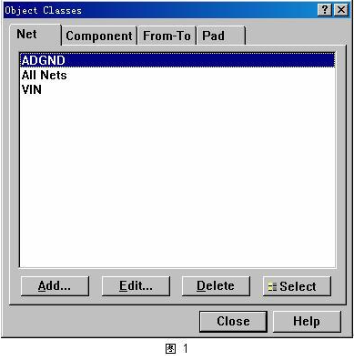
First open a PCB diagram; select the menu “Design–>Classes..” to jump out of the screen in Figure 1.
Here I have pre-defined several Cs, among which “AllNets” is the default category of protel, which includes all networks. If the wiring rules are defined, the default is for this category.
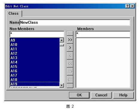
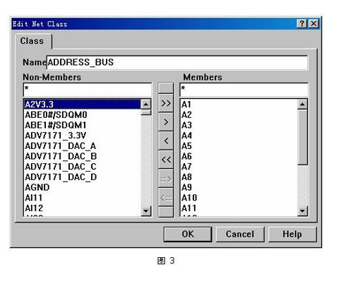
Now I want to add a category “Address_bus” to represent the CPU address bus for this PCB. Press the “Add” button in the screen of Figure 1, select “A0~A19” in the screen of Figure 2, and then select “>” to place these networks in the right subwindow. As shown in Figure 3. In this way, a new PCB network category is established. In the same way, create network categories such as “power” and “data_bus”.
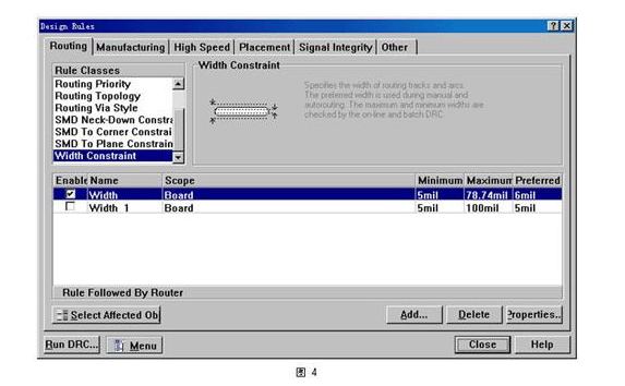
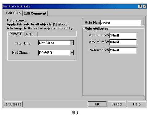
Okay, let’s specify the routing strategy for these network categories respectively. First, let’s specify the routing strategy for the power category. Press the “Add” button in the screen of Figure 4 to add a strategy. As shown in Figure 5, select “NetClass” for “FilterKind” and “POWER” for “NetClass”, and then you can set its line width and other parameters separately. You can also add a proximity restriction rule for the POWER class (since my circuit board is a 4-layer board, I will not set the proximity rule for this project).
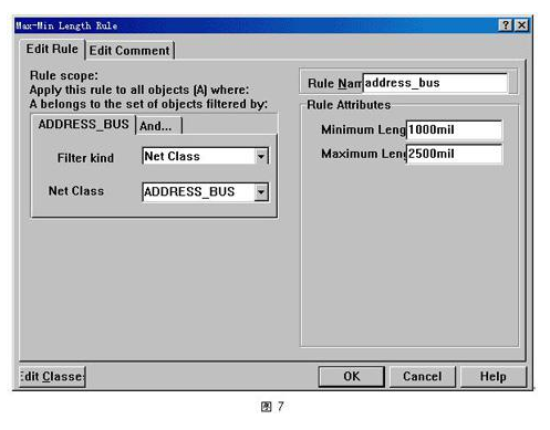

Since my circuit board is a high-speed embedded system, the CPU external bus frequency is about 200MHz. Therefore, the design of the address bus and data bus becomes crucial. The length difference between each address bus cannot be too long, otherwise it will cause transmission delay. However, it is really troublesome to measure the length difference manually, so here you can set a wiring rule for the address bus.
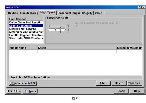
In the wiring rule window of Figure 6, select “LengthConstraint”, the window of Figure 7 pops up, select the “ADDRESS_BUS” class, and you can set the maximum and minimum length of the bus. The window shown in Figure 8 can set the serpentine wiring rule for this NetClass.
After setting the above rules, both manual and automatic wiring will be much simpler. In the process of manual wiring and trimming circuit boards, you don’t have to consider these parameters anymore, because the PCB editor will give a warning if you make a mistake. With this setting, you can set rules for a large number of signal lines at a time, and no longer need to set them one by one. It can save you a lot of time and avoid many low-level mistakes that you shouldn’t make.