PCB Board Edge Connectors: Design, Types, and Applications
Introduction to PCB Edge Connectors
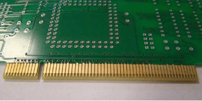
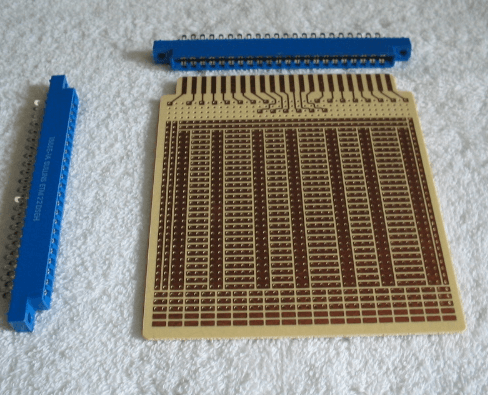
Printed Circuit Board (PCB) edge connectors represent a fundamental interconnection technology that has been widely used in electronic systems for decades. These connectors provide a simple yet effective method for connecting PCBs to other boards or to system backplanes without the need for additional connector components. The edge connector design utilizes the PCB itself as the mating interface, with exposed copper traces along the board’s edge that make contact with corresponding spring-loaded contacts in the receptacle.
Edge connectors offer several advantages in electronic design. They eliminate the cost of separate connector components, reduce the overall parts count in a system, and provide a direct connection path that minimizes signal integrity issues. However, proper design and implementation are crucial for reliable operation. This article explores the various aspects of PCB edge connectors, including their types, design considerations, materials, and applications across different industries.
Types of PCB Edge Connectors
1. Standard Edge Connectors
Standard edge connectors are the most basic form, consisting of exposed copper pads or fingers along one edge of the PCB. These are typically used in consumer electronics and computer peripherals where moderate reliability requirements exist. The fingers are usually gold-plated for better conductivity and corrosion resistance, with common thicknesses ranging from 1 to 3 microns of hard gold.
2. Card Edge Connectors
Card edge connectors are a specialized version designed for higher-density applications. They feature finer pitch contacts and often include keying mechanisms to ensure proper orientation. These are commonly found in memory modules (SIMM, DIMM) and expansion cards (PCI, PCIe). The PCI Express edge connector, for instance, has become a standard in computer hardware with its distinctive notched design.
3. High-Density Edge Connectors
As electronic devices continue to shrink, high-density edge connectors have emerged to meet the need for more contacts in less space. These connectors may have contact pitches as small as 0.5mm and often employ advanced plating technologies like selective gold plating over nickel to maintain reliability while controlling costs.
4. High-Current Edge Connectors
For power applications, specialized high-current edge connectors use wider contact fingers and sometimes multiple layers of copper to handle increased current loads. These are common in power supply units and industrial control systems where currents may exceed 20 amps per contact.
5. RF Edge Connectors
Radio frequency applications require specialized edge connectors that maintain controlled impedance throughout the connection. These often use coplanar waveguide designs with precise spacing to ground planes to minimize signal reflection and loss at microwave frequencies.

Design Considerations for PCB Edge Connectors
1. Finger Geometry and Layout
The design of the contact fingers is critical for reliable connection. Typical finger width ranges from 0.5mm to 2.0mm depending on the application. The spacing between fingers (pitch) commonly varies from 1.27mm to 2.54mm for standard connectors, with high-density versions going down to 0.5mm. Designers must maintain consistent finger width and spacing to ensure proper mating with the receptacle contacts.
2. Plating Specifications
Edge connector fingers require special surface finishing to ensure good conductivity and durability. Common plating options include:
- Electroless Nickel Immersion Gold (ENIG): Provides excellent corrosion resistance and solderability
- Hard Gold: Offers superior wear resistance for high-insertion-cycle applications
- Selective Gold Plating: Reduces cost by plating only the contact areas
- Tin-Lead or Lead-Free Solder: Lower-cost option for less demanding applications
The gold thickness typically ranges from 0.5 to 2.5 microns for commercial applications, with military specifications often requiring thicker plating.
3. Board Edge Preparation
The PCB edge must be precisely machined to ensure smooth insertion and proper contact alignment. Common edge preparation methods include:
- Routing: Standard method using carbide bits
- V-Scoring: Creates a clean break line for separation
- Punching: Used for high-volume production
- Laser Cutting: Provides the highest precision for critical applications
The edge should have a chamfer (typically 30-45 degrees) to facilitate insertion and prevent damage to receptacle contacts.
4. Mechanical Support and Alignment
Proper mechanical support is essential to prevent board flexing that could disrupt connections. Design considerations include:
- Mounting holes near the connector area
- Stiffeners for thin boards
- Guide rails or slots in the receptacle
- Keying mechanisms to prevent incorrect insertion
5. Electrical Considerations
Signal integrity must be maintained through the edge connection:
- Impedance control for high-speed signals
- Proper grounding schemes
- Power distribution for high-current applications
- Shielding for noise-sensitive circuits
Materials and Manufacturing Processes
1. PCB Materials
The base PCB material affects the connector’s performance:
- FR-4: Most common, suitable for general purpose applications
- High-Tg Materials: Better for high-temperature environments
- Polyimide: Excellent for flexible circuits and high-reliability applications
- Rogers or other RF materials: Used for high-frequency edge connectors
2. Contact Materials
The receptacle contacts are typically made from:
- Phosphor Bronze: Common for general purpose connectors
- Beryllium Copper: Higher spring force and durability
- Brass: Lower cost but less durable
3. Plating Processes
Key plating processes include:
- Electroplating: For gold or other metal deposition
- Electroless Plating: For nickel underlayment
- Immersion Plating: For final gold layer
- Selective Plating: Masking techniques to plate only specific areas
Applications of PCB Edge Connectors
1. Computer Hardware
Edge connectors are ubiquitous in computer systems:
- Memory modules (DIMM, SIMM)
- Expansion cards (PCI, AGP, PCIe)
- Storage devices (SSD form factors like M.2)
2. Consumer Electronics
Many consumer products utilize edge connectors:
- Game cartridges
- Printer cartridges
- Smartphone docking stations
3. Industrial Equipment
Industrial applications benefit from edge connectors:
- PLC modules
- Industrial control cards
- Test and measurement equipment
4. Telecommunications
Telecom systems employ edge connectors in:
- Line cards
- Network interface modules
- Backplane connections
5. Automotive Electronics
Modern vehicles use edge connectors in:
- Engine control modules
- Infotainment systems
- Sensor interfaces
Reliability and Maintenance Considerations
1. Insertion Cycles
The expected number of insertion cycles affects design choices:
- Consumer devices: 50-100 cycles
- Commercial equipment: 500-1,000 cycles
- Military/aerospace: 10,000+ cycles
2. Environmental Factors
Environmental conditions must be considered:
- Temperature range
- Humidity exposure
- Vibration and shock
- Chemical exposure
3. Contact Wear Mechanisms
Common wear mechanisms include:
- Fretting corrosion
- Contact wear
- Plating degradation
- Contamination buildup
4. Maintenance Practices
Proper maintenance extends connector life:
- Regular cleaning
- Proper insertion/extraction techniques
- Storage conditions for unused boards
- Inspection procedures
Future Trends in Edge Connector Technology
1. Higher Density Designs
Ongoing miniaturization drives the need for:
- Finer pitch contacts
- Higher layer count boards
- Advanced plating technologies
2. High-Speed Signal Integrity
As data rates increase, edge connectors must address:
- Improved impedance control
- Reduced crosstalk
- Better shielding techniques
3. Advanced Materials
New materials are being developed:
- Nanocomposite platings
- Graphene-based contacts
- High-performance dielectric materials
4. Smart Connectors
Integration of intelligence into connectors:
- Embedded sensors
- Self-monitoring capabilities
- Active alignment features
Conclusion
PCB edge connectors remain a vital interconnection technology despite the development of alternative solutions. Their simplicity, cost-effectiveness, and direct signal path continue to make them attractive for numerous applications. Proper design, material selection, and manufacturing processes are essential to ensure reliable performance throughout the product lifecycle.
As electronic systems evolve, edge connector technology must adapt to meet new challenges in density, speed, and reliability. The future will likely see continued innovation in materials, plating technologies, and mechanical designs to keep pace with the demands of modern electronics.
Understanding the principles and best practices of PCB edge connector design enables engineers to create robust, reliable interconnections that meet the needs of today’s complex electronic systems while remaining cost-effective and manufacturable at scale.


