PCB Design Considerations for Optimal Soldering Process
Introduction
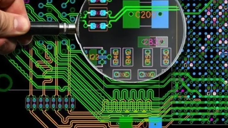
Printed Circuit Board (PCB) design plays a critical role in determining the quality, reliability, and manufacturability of electronic products. While much attention is often given to electrical performance and signal integrity, the soldering aspects of PCB design are equally important yet frequently overlooked. Proper consideration of soldering requirements during the design phase can significantly improve production yields, reduce manufacturing defects, and enhance the long-term reliability of electronic assemblies.
This article provides a comprehensive guide to the key soldering process requirements that should be incorporated into PCB design. We will examine design considerations for various soldering methods (including wave soldering, reflow soldering, and hand soldering), component placement strategies, pad and land pattern design, thermal management, and other critical factors that influence soldering quality.
1. Soldering Method Considerations
1.1 Wave Soldering Design Requirements
Wave soldering remains a common process for through-hole components and some surface-mount devices. Design considerations include:
- Component orientation: All similar components should be oriented in the same direction (preferably perpendicular to the solder wave flow) to ensure even soldering
- Shadowing effects: Larger components should not precede smaller ones in the wave direction to prevent solder shadowing
- Board spacing: Maintain at least 3mm clearance between the PCB edge and components to allow for proper clamping
- Thermal relief: Use thermal relief connections for ground/power planes to prevent heat sinking issues
- Solder thieves: Incorporate solder thieves (additional pads) at the end of the solder wave flow path for multi-row connectors
1.2 Reflow Soldering Design Requirements
Reflow soldering is the primary method for surface-mount technology (SMT). Key design aspects include:
- Component placement: Ensure adequate spacing between components (typically ≥0.5mm) to allow for proper solder paste deposition and reflow
- Thermal mass distribution: Balance thermal masses across the board to prevent uneven heating during reflow
- Component size gradation: Place smaller components away from larger ones to prevent shadowing in the reflow oven
- Pad symmetry: Design symmetrical pads for chip components to prevent tombstoning (where one end lifts during reflow)
1.3 Mixed Technology Considerations
For boards containing both through-hole and surface-mount components:
- Component placement strategy: Group SMT components on one side and through-hole on the other when possible
- Process sequence: Design for wave soldering after reflow when both processes are required
- Solder mask requirements: Ensure proper solder mask dams between SMT pads to prevent bridging
2. Pad and Land Pattern Design
2.1 Surface Mount Device (SMD) Pads
- Follow IPC-7351 standards for land pattern geometries
- Consider solder paste volume requirements when designing pad sizes
- For fine-pitch components (≤0.5mm pitch), use rectangular pads with proper spacing
- Incorporate solder mask defined (SMD) or non-solder mask defined (NSMD) pads appropriately
2.2 Through-Hole Pads
- Hole sizes should be 0.2-0.3mm larger than component leads for proper solder wicking
- Annular rings should be ≥0.15mm for standard reliability, ≥0.25mm for high reliability
- For plated-through holes (PTH), consider aspect ratios (board thickness to hole diameter) ≤8:1 for reliable plating
2.3 Solder Mask Design
- Maintain solder mask dams ≥0.1mm between adjacent pads
- Ensure proper solder mask clearance around pads (typically 0.05-0.1mm expansion)
- Use solder mask to control solder flow and prevent bridging
- Consider solder mask thickness (typically 0.01-0.02mm) in the design
3. Component Placement and Orientation
3.1 General Placement Guidelines
- Maintain minimum spacing between components (typically 0.5mm for reflow, 1mm for wave)
- Avoid placing tall components next to very small ones
- Group components with similar thermal requirements together
- Consider automated optical inspection (AOI) requirements in placement
3.2 Orientation Considerations
- Align all polarized components in the same direction for easier inspection
- Orient rectangular chip components parallel to board edges
- For wave soldering, orient components perpendicular to the solder wave direction
- Consider stencil printing direction when placing fine-pitch components
4. Thermal Management for Soldering
4.1 Thermal Relief Design
- Use thermal relief connections (spokes) for pads connected to large copper areas
- Typical thermal relief design: 4 spokes, 0.2-0.3mm width
- Ensure adequate thermal relief for ground/power connections to prevent heat sinking
4.2 Balanced Thermal Mass
- Distribute copper evenly across layers to prevent warpage during reflow
- Consider thermal mass differences between board areas that may lead to uneven heating
- Use copper thieving (dummy copper) in sparse areas to balance thermal mass
4.3 Heat-Sensitive Components
- Place temperature-sensitive components away from high-thermal-mass areas
- Consider using thermal barriers for components with strict temperature limits
- Account for different component temperature tolerances in the layout
5. Design for Manufacturing (DFM) Considerations
5.1 Fiducial Marks and Tooling
- Include at least three global fiducial marks (1mm diameter preferred)
- Place fiducials in asymmetrical pattern for board orientation detection
- Maintain clear area (no solder mask) around fiducials
- Include tooling holes (typically 3.0-3.2mm diameter) at board corners
5.2 Panelization Considerations
- Include adequate breakaway tabs or mouse bites for depaneling
- Maintain consistent board spacing in panels (typically 3-5mm)
- Consider routing or scoring requirements in panel design
- Include tooling strips with test coupons when panelizing
5.3 Testability Considerations
- Provide adequate test points (minimum 0.8mm diameter preferred)
- Space test points ≥1.27mm apart for flying probe testing
- Consider in-circuit test (ICT) fixture requirements in the layout
- Ensure test points are accessible and not obscured by components
6. Special Considerations for Advanced Technologies
6.1 Fine-Pitch and BGA Components
- Follow manufacturer recommendations for pad sizes and spacing
- Incorporate proper via-in-pad design when needed
- Consider solder mask defined pads for very fine pitch (<0.4mm)
- Include adequate escape routing for high-density packages
6.2 QFN and LGA Packages
- Use exposed thermal pads with proper via patterns
- Ensure proper solder mask clearance around package edges
- Incorporate corner marking for orientation identification
- Consider paste volume requirements for center thermal pads
6.3 High-Power Components
- Design pads with adequate current-carrying capacity
- Incorporate thermal vias under high-power devices
- Consider solder voiding requirements for large pads
- Account for different thermal expansion coefficients

7. Documentation and Communication
7.1 Assembly Drawing Requirements
- Clearly indicate component orientations and polarities
- Specify special soldering requirements or instructions
- Identify any areas requiring hand soldering or rework
- Note any components with specific temperature limitations
7.2 Bill of Materials (BOM) Considerations
- Include complete part numbers and manufacturer information
- Specify component moisture sensitivity levels (MSL)
- Note any special soldering requirements for specific components
- Identify alternative parts with identical footprints when possible
7.3 Communication with Manufacturers
- Provide complete fabrication and assembly drawings
- Discuss any special soldering process requirements early
- Clarify acceptability criteria for solder joints
- Understand the manufacturer’s capabilities and limitations
Conclusion
Effective PCB design for optimal soldering requires careful consideration of numerous factors throughout the design process. By incorporating these soldering process requirements early in the design phase, engineers can significantly improve manufacturing yields, reduce production costs, and enhance product reliability. The key is to balance electrical performance needs with manufacturability requirements, while maintaining awareness of the capabilities and limitations of modern soldering processes.
As electronic components continue to evolve with smaller sizes, higher densities, and more complex packages, the importance of designing for soldering will only increase. Staying current with IPC standards, manufacturing capabilities, and emerging soldering technologies will enable designers to create PCBs that are not only functionally excellent but also manufacturing-friendly and reliable throughout their service life.