Pcb digital circuit anti-interference
1 Suppress interference source
Suppressing interference source means reducing du/dt and di/dt of interference source as much as possible. This is the most important and most important principle in anti-interference design, which often achieves twice the result with half the effort. Reducing du/dt of interference source is mainly achieved by connecting capacitors in parallel at both ends of interference source. Reducing di/dt of interference source is achieved by connecting inductor or resistor in series with interference source loop and adding freewheeling diode.
Common measures to suppress interference source are as follows:
(1) Add freewheeling diode to relay coil to eliminate back electromotive force interference generated when disconnecting coil. Only adding freewheeling diode will delay the disconnection time of relay. After adding voltage regulator diode, relay can operate more times per unit time.
(2) Connect spark suppression circuit (usually RC series circuit, resistor is generally selected from several K to tens of K, capacitor is selected from 0.01uF) at both ends of relay contact to reduce the influence of electric spark.
(3) Add filter circuit to motor, and pay attention to the short leads of capacitor and inductor.
(4) Each IC on the circuit board should be connected in parallel with a 0.01μF~0.1μF high-frequency capacitor to reduce the impact of the IC on the power supply. Pay attention to the wiring of the high-frequency capacitor. The connection line should be close to the power supply end and as thick and short as possible. Otherwise, it is equivalent to increasing the equivalent series resistance of the capacitor, which will affect the filtering effect.
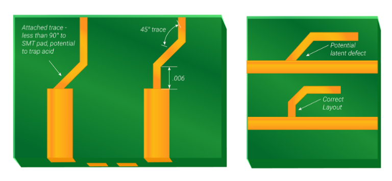
(5) Avoid 90-degree folds when wiring to reduce high-frequency noise emission.
(6) Connect an RC suppression circuit at both ends of the thyristor to reduce the noise generated by the thyristor (this noise may break down the thyristor when it is serious).
2 According to the propagation path of interference, it can be divided into two categories:
conducted interference and radiated interference.
The so-called conducted interference refers to the interference transmitted to the sensitive device through the wire. The frequency band of high-frequency interference noise is different from that of the useful signal. The propagation of high-frequency interference noise can be cut off by adding a filter on the wire, and sometimes it can be solved by adding an isolation optocoupler. Power supply noise is the most harmful and should be handled with special attention. The so-called radiated interference refers to the interference transmitted to the sensitive device through space radiation. The general solution is to increase the distance between the interference source and the sensitive device, isolate them with a ground wire, and add a shield to the sensitive device.
Common measures to cut off the interference propagation path are as follows:
(1) Fully consider the impact of the power supply on the microcontroller.
If the power supply is well made, the anti-interference of the entire circuit is mostly solved. Many microcontrollers are very sensitive to power supply noise. It is necessary to add a filter circuit or a voltage regulator to the microcontroller power supply to reduce the interference of power supply noise on the microcontroller. For example, a π-shaped filter circuit can be formed using magnetic beads and capacitors. Of course, 100Ω resistors can also be used instead of magnetic beads when the conditions are not high.
(2) If the I/O port of the microcontroller is used to control noisy devices such as motors,
isolation should be added between the I/O port and the noise source (add a π-shaped filter circuit). To control noisy devices such as motors, isolation should be added between the I/O port and the noise source (add a π-shaped filter circuit).
(3) Pay attention to the crystal oscillator wiring.
Keep the crystal oscillator and the microcontroller pins as close as possible, isolate the clock area with a ground wire, and ground and fix the crystal oscillator shell. This measure can solve many difficult problems.
(4) Reasonably divide the circuit board into strong and weak signals, digital and analog signals.
Keep interference sources (such as motors, relays) and sensitive components (such as microcontrollers) as far away as possible.
(5) Use a ground wire to isolate the digital area from the analog area.
The digital ground and analog ground should be separated, and finally connected to the power ground at one point. The A/D and D/A chip wiring also follows this principle. The manufacturer has considered this requirement when allocating the A/D and D/A chip pin arrangement.
(6) The ground wires of the microcontroller and high-power devices should be grounded separately to reduce mutual interference
High-power devices should be placed at the edge of the circuit board as much as possible.
(7) Use anti-interference components such as magnetic beads, magnetic rings, power filters, and shielding covers in key places such as the microcontroller I/O port, power line, and circuit board connection line to significantly improve the circuit’s anti-interference performance.