
PCB E-Test: Flying Probe vs Fixture Testing Cost and Coverage Analysis
When prototype boards arrive from assembly, choosing between flying probe and fixture testing directly impacts NPI timeline and per-unit costs. The break-even point sits around 500-1000 boards but shifts based on board complexity, design stability, and test access.
What Flying Probe and Fixture Testing Measure
Both methods perform electrical testing (E-test) to catch fabrication and assembly defects, verifying continuity, isolation, and component presence.
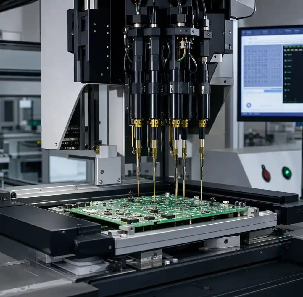
Flying probe uses 4-8 movable test heads on X-Y stages contacting test points sequentially, measuring resistance, capacitance, and component values.
Fixture testing (ICT) uses custom fixtures with spring-loaded pogo pins contacting every test point simultaneously—hundreds of pins enabling parallel testing in 3-15 seconds per board.
The trade-off: flying probe eliminates fixture cost but sacrifices speed. Fixture testing requires high upfront investment with minimal per-board test time.
Cost Structure Comparison
Flying probe carries zero NRE. You send Gerbers and a netlist, testing starts in 1-3 days. Fixture testing requires custom fixture design and fabrication—$3,000-$15,000 for simple boards, up to $50,000+ for complex designs.
| Cost Factor | Flying Probe | Fixture Testing (ICT) |
|---|---|---|
| Fixture NRE | $0 | $3,000-$50,000 |
| Program setup | 1-3 days | 1-2 weeks |
| Per-board test time | 3-8 minutes | 10-60 seconds |
| Per-board cost | $5-$15 | $0.50-$3 (after NRE) |
| Design change cost | Reprogram (1-4 hrs) | Fixture rework ($500-$5,000) |
| Break-even volume | N/A | 500-2,000 boards |
That per-board time difference compounds fast. Five-minute flying probe test means 12 boards per hour. Thirty-second fixture test delivers 120 boards per hour. At 1,000+ units, fixture testing pays back NRE through labor savings.
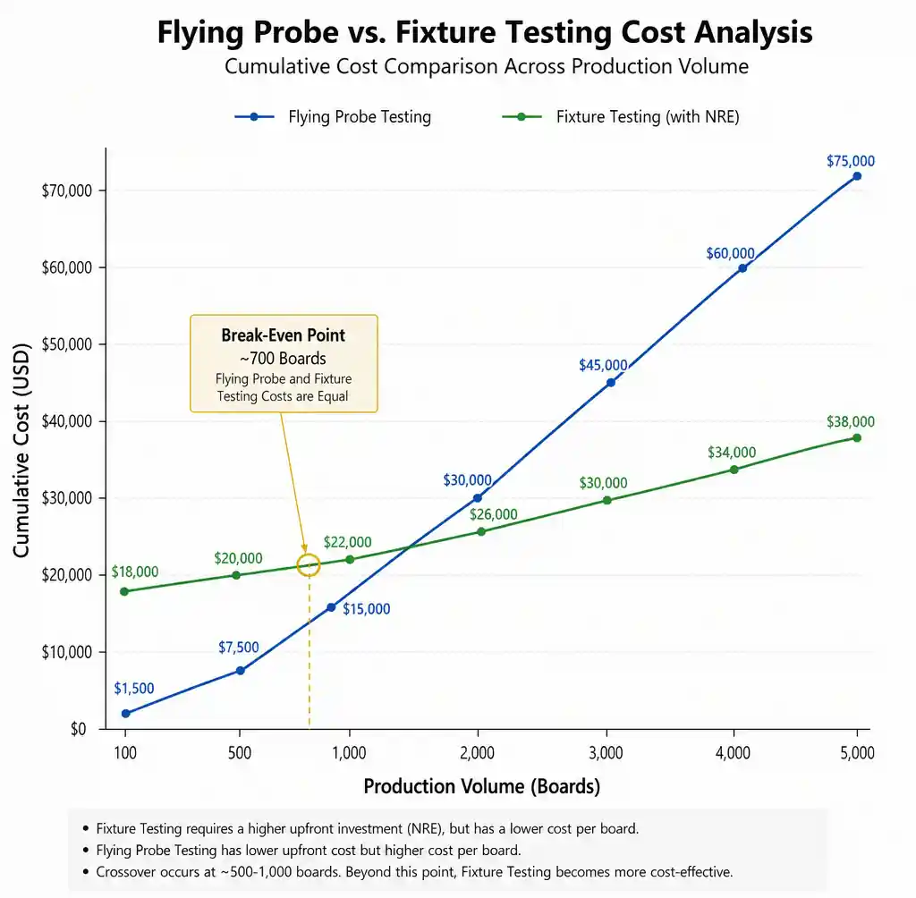
But this assumes frozen designs. Most NPI projects revise layouts 3-5 times before production. Design changes mean reprogramming flying probe (hours) versus fixture rework or rebuild (weeks and thousands of dollars).
Test Coverage: The Hidden Variable
Coverage percentage—the proportion of nets and components tested—determines what defects slip through. Both methods claim 85-98% coverage, but actual numbers depend on physical test point access.
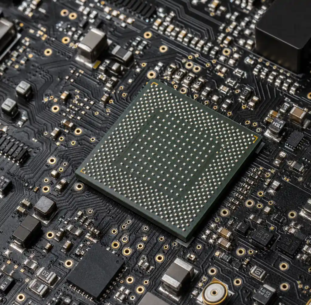
Flying probe achieves 85-95% coverage on typical boards. Double-sided probing reaches nodes requiring via stitching with single-sided access. Dense BGAs, shielded components, and blocked test points remain inaccessible. Probes need 20-40 mil clearance around each point.
Fixture testing pushes 90-98% coverage when fixture design accommodates every accessible node. Fixtures contact points unreachable by flying probe but require dedicated test points consuming board space. Designs without test points (common in IoT/wearables) gain no coverage advantage.
| Coverage Factor | Flying Probe | Fixture Testing |
|---|---|---|
| Typical coverage | 85-95% | 90-98% |
| Double-sided access | Standard | Requires double-sided fixture (+40-60% cost) |
| BGA underneath | Limited (perimeter only) | Limited (needs via test points) |
| Min test point pitch | 20-30 mils | 50-75 mils standard, 30 mils (+cost) |
| Design change impact | Reprogram (coverage maintained) | May lose coverage if points move |
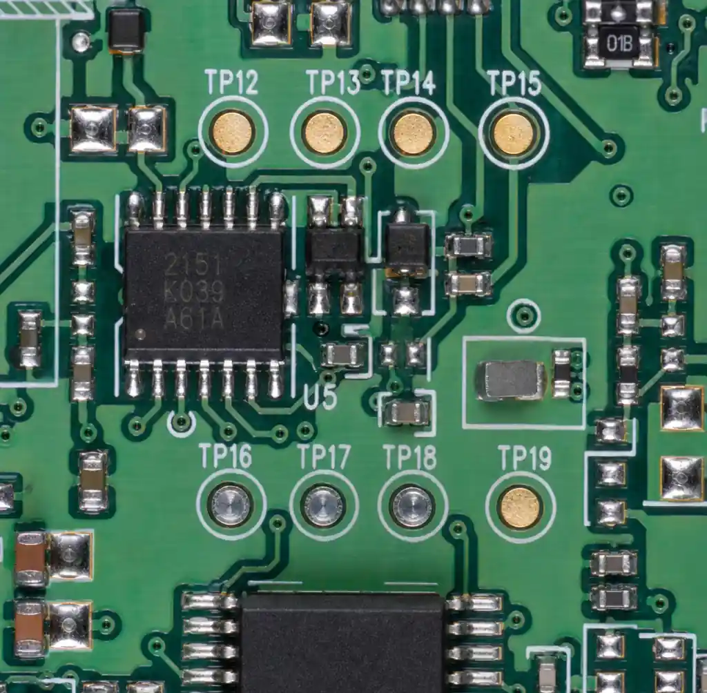
If your design includes test points for fixtures, flying probe uses those same points with no layout changes. If lacking test points, adding them for flying probe still provides better ROI than for a 200-board fixture run.
When Flying Probe Makes Sense
Flying probe works best for prototypes, NPI builds, and runs below 500 units where designs change frequently. It’s ideal for multiple derivative designs—testing 10 variants costs the same as one.
Fast-moving designs: If layouts change every 2-3 weeks, fixture testing can’t keep up. Programs waste $30,000+ on unused fixtures before designs stabilize.
Low-volume production: Boards in 50-500 unit batches never justify fixture investment. Medical prototypes, aerospace units, and industrial systems benefit from zero NRE.
High mix, low volume: Contract manufacturers running 50+ designs monthly can’t afford fixture inventory. Flying probe stores programs digitally—no physical storage or maintenance.
Test point-constrained designs: Miniaturized products lack space for 50-75 mil pitch. Flying probe’s 20-30 mil capability accesses denser layouts.
Rapid failure analysis: Field returns need 1-2 day verification. Fixtures require 1-2 week storage retrieval and re-validation.
When Fixture Testing Pays Off
Once designs stabilize and volume crosses 1,000 units yearly, fixture testing economics improve dramatically. The cost gap widens: 10,000 boards with flying probe at $8 each costs $80,000. Same volume with fixture testing runs $5,000 NRE plus $15,000 per-board—$20,000 total.
Stable, high-volume products: Consumer electronics, automotive modules, and telecom equipment above 2,000 units annually recover fixture NRE in first run. At 10,000+ units, fixtures cut per-board costs 70-85%.
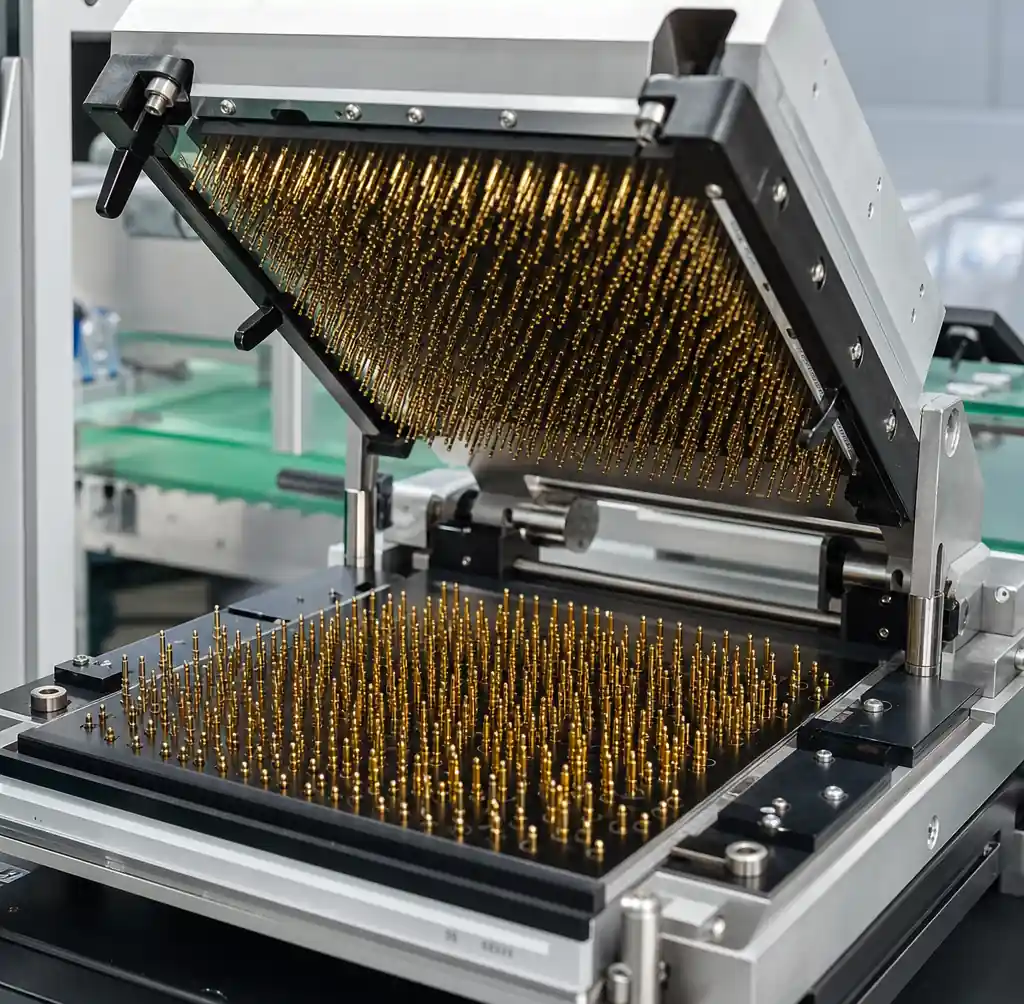
High-value boards: When board cost exceeds $500, field failure costs dwarf test expense. Fixture testing enables 100% screening without bottlenecking—960 boards per shift versus 96 with flying probe.
Automotive and medical compliance: Industries requiring documented procedures favor fixtures. ICT provides consistent contact force and traceability data satisfying IATF 16949 and ISO 13485.
Powered testing: Fixtures integrate boundary scan (JTAG), functional sequences, and powered measurements for boot-up and interface verification.
Hybrid Approaches in Practice
Many programs use both methods at different stages.
Pre-production with flying probe, production with fixtures: Validate design margins through 10-50 flying probe tests during NPI, then commit to fixtures once design freezes. This catches test point access issues before fixture investment.
Flying probe for variants, fixtures for base: Product families use fixture testing on high-volume base SKUs while testing low-volume derivatives with flying probe.
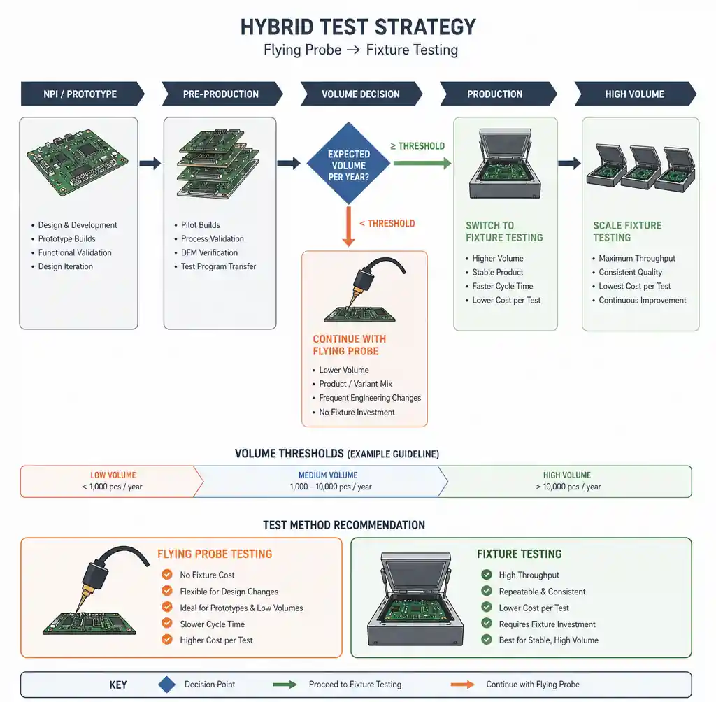
Fixture for primary nets, flying probe for secondary: Some use simplified fixtures targeting critical power, ground, and high-speed signals (60-70% coverage) with flying probe testing less-critical I/O and peripherals. This reduces fixture complexity while maintaining thorough validation.
Programming and Setup Reality Check
Flying probe programs generate semi-automatically from netlist and CAD data. Typical 4-layer boards with 200 components need 4-8 hours: netlist import, sequence definition, clearance verification. Complex boards extend to 16-24 hours.
Fixture programs take 1-2 weeks for mechanical design, fabrication, and debug. But once complete, fixtures handle design-for-test issues.
Revision changes reveal the difference. Flying probe updates in 1-4 hours for minor changes, 4-8 for major ones. Fixtures range from pin disables ($0, 30 minutes) to rebuilds ($3,000-$8,000, 1-2 weeks).
Making the Decision: A Framework
Start with annual volume forecast over 3-5 years, not just first production run. A 200-board prototype might scale to 5,000 units annually—fixtures become viable in year two.
Calculate total cost of ownership: NRE, revision costs, program setup, and opportunity cost of slow test cycles.
| Scenario | Recommended Method | Key Reason |
|---|---|---|
| Prototype/NPI (<500 boards lifetime) | Flying probe | Zero NRE, fast changes |
| Production (>2,000 boards/year, stable) | Fixture testing | NRE recovery through speed |
| Medium volume (500-2,000/year) | Flying probe initially, fixture at 1,000 | Minimize risk, preserve scale path |
| High-mix contract mfg | Flying probe | No fixture inventory |
| Medical/automotive (powered test) | Fixture with functional test | Compliance and coverage |
| Dense BGA, limited access | Flying probe | Access advantage |
Consider test access during schematic and layout, not after assembly returns. Adding test points costs $0 in design but thousands in rework or compromised coverage later.
Test Coverage Optimization Techniques
Maximizing coverage requires design intent, not just test method selection.
Test point design rules improving coverage for both methods:
- 20 mil (0.5mm) diameter minimum for flying probe, 30-40 mil for fixtures
- 50 mil (1.27mm) keepout clearance (no vias, no traces)
- Test points on both board sides for double-sided access
- Via-in-pad provides test access for dense BGA fanouts
- One test point per net minimum; critical nets benefit from multiple points
Component placement affects test access as much as test point location. Tall components (capacitors, connectors, heat sinks) block flying probe access in a radius 2-3x their height. Fixtures handle tall components better through clearance holes but lose pin density.
Soldermask-defined test points reduce false failures from probe slippage. A 30-mil opening over 40-mil pad provides mechanical registration while maintaining contact reliability.
FAQ
Q: Can flying probe test assembled boards or only bare PCBs?
A: Flying probe tests both bare boards (fabrication verification) and assembled boards (post-PCBA electrical testing). Bare board testing catches fabrication defects. Assembled board testing verifies component presence, polarity, and values. However, components near test pads block probe access.
Q: What’s the minimum order quantity for fixture testing to make economic sense?
A: Break-even typically occurs at 500-1,000 boards total. Simple 2-4 layer boards with $3,000 fixtures break even around 500 units. Complex multilayer boards with $15,000 fixtures need 1,500-2,000 units. Calculate by dividing fixture NRE by per-board cost difference.
Q: How do I improve test coverage without adding more test points?
A: Use vias as test points where exposed (not tented). Place test points on power and ground plane breakouts. Double-sided access increases coverage 10-20%. For HDI boards, via-in-pad structures serve dual purposes: thermal management and test access.
Q: Does flying probe testing damage boards or components?
A: No, when programmed correctly. Probe force is 25-100 grams per probe—calibrated to contact pads without damaging soldermask or components. Problems arise from mis-programmed probes contacting wrong locations. First-article testing includes visual probe mark inspection.
Q: Can I switch from flying probe to fixture testing mid-production?
A: Yes, common when volume exceeds forecasts. Design for fixture testing from the start—include compatible test points even using flying probe initially. This preserves fixture option without board redesign. Switching from fixture to flying probe is harder because fixture layouts may lack required test point density.
Q: What test coverage percentage should I target?
A: Industry targets: 85% minimum for commercial products, 95% for automotive, 98% for medical devices. Achieving these requires planning test access during design. Dense BGA layouts may only reach 70-80%—supplement with AOI and X-ray to catch assembly defects electrical testing misses.
Conclusion
Flying probe testing removes fixture investment and keeps NPI processes agile. Fixture testing delivers production efficiency once design and volume justify the cost. The break-even point sits around 500-1,000 boards, but design stability and test access shift that number significantly.
The decision isn’t permanent. Starting with flying probe during prototyping preserves the option to transition to fixture testing when volume warrants. The reverse—abandoning fixture investment—rarely makes economic sense.
When planning test strategy, evaluate total program costs over product lifecycle, not just immediate builds. Account for design revisions, derivative products, and field failure costs from inadequate coverage. Balance upfront investment against per-unit costs while maintaining necessary electrical validation confidence.
At Andwin Circuits, we provide both flying probe and fixture testing through comprehensive PCB assembly services. Our engineering team helps customers navigate this decision during DFM review, ensuring test point access and coverage expectations align with production volume and budget.