Pcb header
Understanding The Basics Of PCB Headers
Printed Circuit Board (PCB) headers are essential components in the realm of electronics, serving as the interface between various parts of a circuit. These connectors are pivotal in ensuring that electrical signals and power are transmitted efficiently and reliably across different sections of a PCB. Understanding the basics of PCB headers is crucial for anyone involved in electronics design and manufacturing, as these components play a significant role in the functionality and reliability of electronic devices.
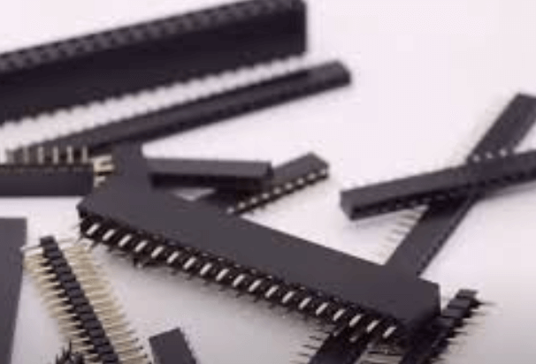
PCB headers come in various shapes, sizes, and configurations, each tailored to specific applications and requirements.
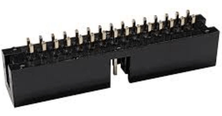
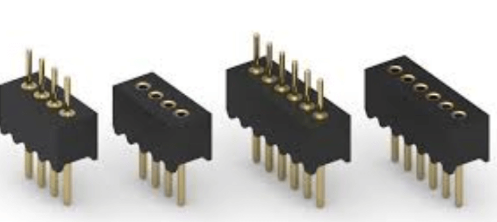
Typically, they consist of a series of metal pins arranged in a row or grid pattern, which are then soldered onto the PCB. These pins can be male or female, with male headers featuring protruding pins and female headers having corresponding sockets. The choice between male and female headers depends on the design requirements and the type of connection needed.
One of the primary considerations when selecting a PCB header is the pitch, which refers to the distance between the centers of adjacent pins.
Common pitch sizes include 2.54mm (0.1 inch), 2.00mm, and 1.27mm, among others. The pitch size is critical as it determines the compatibility of the header with other components and connectors. For instance, a 2.54mm pitch is widely used in prototyping and hobbyist projects due to its compatibility with standard breadboards and jumper wires.
In addition to pitch size, the number of pins and the arrangement of these pins are also important factors.
Headers can be single-row or multi-row, with the latter providing more connection points in a compact space. The number of pins can range from a few to several dozen, depending on the complexity of the circuit and the amount of data or power that needs to be transmitted. Furthermore, headers can be straight or right-angled, with right-angled headers being useful in situations where space constraints or specific design layouts necessitate a change in the direction of the connection.
Another critical aspect of PCB headers is their current and voltage rating.
These ratings indicate the maximum electrical load that the header can safely handle. Exceeding these ratings can lead to overheating, damage to the header, or even failure of the entire circuit. Therefore, it is essential to choose headers that meet or exceed the electrical requirements of the application.
Moreover, the material and plating of the pins are also significant considerations.
Typically, the pins are made of brass or phosphor bronze, which are then plated with materials such as tin, gold, or nickel. The choice of plating material affects the conductivity, corrosion resistance, and overall durability of the header. Gold plating, for example, offers excellent conductivity and resistance to oxidation, making it suitable for high-reliability applications, albeit at a higher cost.
In conclusion, PCB headers are indispensable components in electronic circuits, providing reliable connections between different parts of a PCB. When selecting a PCB header, it is essential to consider factors such as pitch size, number of pins, arrangement, current and voltage ratings, and material and plating. By understanding these basics, designers and engineers can make informed decisions that ensure the optimal performance and reliability of their electronic devices.
How To Choose The Right PCB Header For Your Project
Selecting the appropriate PCB header for your project is a critical step in ensuring the reliability and functionality of your electronic design. A PCB header, which serves as a connector between different components or boards, comes in various types, sizes, and configurations. Therefore, understanding the key factors to consider when choosing a PCB header is essential for achieving optimal performance and compatibility.
To begin with, it is important to identify the specific requirements of your project.
This includes understanding the electrical and mechanical specifications, such as current rating, voltage rating, and the number of pins needed. The current rating of a PCB header determines the maximum current it can safely carry without overheating or causing damage. Similarly, the voltage rating indicates the maximum voltage the header can handle. Ensuring that these ratings align with your project’s requirements is crucial to prevent potential failures.
Another significant factor to consider is the physical configuration of the PCB header.
Headers come in various forms, including single-row, double-row, and right-angle configurations. The choice of configuration depends on the layout and space constraints of your PCB design. For instance, single-row headers are suitable for applications with limited space, while double-row headers provide more connection points in a compact area. Right-angle headers are ideal for situations where vertical space is restricted, and a horizontal connection is necessary.
In addition to configuration, the pitch of the PCB header is a vital consideration.
Pitch refers to the distance between the centers of adjacent pins. Common pitch sizes include 2.54mm, 2.00mm, and 1.27mm. The pitch size must match the corresponding connectors and components to ensure a secure and reliable connection. Mismatched pitch sizes can lead to poor connections, signal integrity issues, and potential damage to the components.
Material selection is another critical aspect when choosing a PCB header.
The materials used in the construction of the header, such as the housing and pins, affect its durability, conductivity, and resistance to environmental factors. Typically, headers are made from materials like phosphor bronze or brass, which offer good conductivity and mechanical strength. The housing is often made from thermoplastic materials that provide insulation and resistance to high temperatures. It is essential to select materials that can withstand the operating conditions of your project, including temperature variations, humidity, and potential exposure to corrosive substances.
Furthermore, the method of mounting the PCB header onto the board is an important consideration.
There are two primary mounting methods: through-hole and surface-mount. Through-hole headers are inserted into drilled holes on the PCB and soldered on the opposite side, providing strong mechanical bonds and reliable connections. Surface-mount headers, on the other hand, are soldered directly onto the surface of the PCB, offering a more compact and lightweight solution. The choice between these methods depends on the specific requirements of your project, including mechanical strength, space constraints, and manufacturing processes.
Lastly, it is advisable to consider the availability and compatibility of mating connectors.
Ensuring that the chosen PCB header has compatible connectors readily available can save time and effort during the assembly process. Additionally, considering the ease of assembly and disassembly can be beneficial for projects that require frequent maintenance or upgrades.
In conclusion, selecting the right PCB header for your project involves careful consideration of various factors, including electrical and mechanical specifications, physical configuration, pitch size, material selection, mounting method, and compatibility with mating connectors. By thoroughly evaluating these aspects, you can ensure a reliable and efficient connection in your electronic design, ultimately contributing to the success of your project.
Common Mistakes To Avoid When Using PCB Headers
Printed Circuit Board (PCB) headers are essential components in electronic design, providing a reliable means of connecting various parts of a circuit. However, despite their widespread use, there are several common mistakes that engineers and hobbyists alike often make when incorporating PCB headers into their projects. Understanding these pitfalls can help ensure a more efficient and reliable design.
One frequent mistake is the improper selection of the header type.
PCB headers come in various forms, such as single-row, double-row, right-angle, and surface-mount. Choosing the wrong type can lead to connectivity issues and mechanical instability. For instance, using a single-row header when a double-row is required can result in insufficient connections, compromising the circuit’s functionality. Therefore, it is crucial to carefully consider the specific requirements of your project and select the appropriate header type accordingly.
Another common error is neglecting the current and voltage ratings of the headers.
Each header is designed to handle a specific range of electrical parameters. Exceeding these limits can cause overheating, leading to potential damage or failure of the component. To avoid this, always check the manufacturer’s specifications and ensure that the headers you choose can handle the expected electrical load of your circuit.
Furthermore, improper soldering techniques can also pose significant problems.
Cold solder joints, where the solder does not properly adhere to the header pins, can result in intermittent connections or complete circuit failure. To mitigate this risk, it is essential to use the correct soldering temperature and technique. Preheating the PCB and using flux can help achieve a more reliable solder joint. Additionally, inspecting the solder joints for any signs of defects, such as cracks or voids, can prevent future issues.
In addition to soldering, the physical placement of the headers on the PCB is another area where mistakes are often made.
Placing headers too close to other components can create difficulties during assembly and maintenance. It can also lead to accidental short circuits if the pins come into contact with adjacent components. To avoid this, ensure that there is adequate spacing around the headers, allowing for easy access and reducing the risk of shorts.
Moreover, overlooking the importance of proper alignment can lead to significant challenges.
Misaligned headers can cause difficulties when connecting mating connectors, potentially damaging the pins or the connectors themselves. Using alignment tools or fixtures during the soldering process can help maintain the correct orientation and spacing of the headers, ensuring a more reliable connection.
Another critical aspect to consider is the mechanical stress on the headers.
Excessive force during insertion or removal of connectors can damage the header pins or the PCB itself. To prevent this, it is advisable to use headers with appropriate mechanical support, such as through-hole headers with additional mounting points. This can help distribute the mechanical load more evenly and reduce the risk of damage.
Lastly, failing to account for environmental factors can also lead to issues with PCB headers.
Factors such as temperature fluctuations, humidity, and exposure to corrosive substances can affect the performance and longevity of the headers. Selecting headers with appropriate environmental ratings and using protective coatings can help mitigate these risks.
In conclusion, while PCB headers are fundamental components in electronic design, several common mistakes can compromise their effectiveness. By carefully selecting the appropriate header type, adhering to electrical ratings, employing proper soldering techniques, ensuring adequate spacing and alignment, considering mechanical stress, and accounting for environmental factors, you can avoid these pitfalls and achieve a more reliable and efficient design.

Innovative Applications Of PCB Headers In Modern Electronics
Printed Circuit Board (PCB) headers have become indispensable components in modern electronics, serving as critical connectors that facilitate the seamless integration of various electronic modules. These headers, which consist of rows of pins or sockets, are designed to connect different parts of a circuit, enabling efficient communication and power distribution. As technology continues to advance, the innovative applications of PCB headers are becoming increasingly diverse, reflecting their versatility and importance in the electronics industry.
One of the most prominent applications of PCB headers is in the realm of consumer electronics.
Devices such as smartphones, tablets, and laptops rely heavily on these connectors to ensure reliable performance and compact design. PCB headers enable the connection of various internal components, such as the motherboard, battery, and display, thereby contributing to the overall functionality and miniaturization of these devices. The ability to create compact and efficient designs is crucial in the competitive consumer electronics market, where space-saving and performance are paramount.
In addition to consumer electronics, PCB headers play a vital role in the automotive industry.
Modern vehicles are equipped with numerous electronic systems, including advanced driver-assistance systems (ADAS), infotainment systems, and engine control units (ECUs). PCB headers facilitate the integration of these systems by providing robust and reliable connections between different electronic modules. This ensures that the vehicle’s electronic systems operate seamlessly, enhancing safety, performance, and user experience. Furthermore, the automotive industry’s shift towards electric and autonomous vehicles has further underscored the importance of PCB headers in supporting complex electronic architectures.
The medical field is another area where PCB headers have found innovative applications.
Medical devices, such as diagnostic equipment, patient monitoring systems, and wearable health devices, require precise and reliable electronic connections. PCB headers enable the integration of sensors, processors, and communication modules, ensuring accurate data collection and transmission. This is particularly important in critical medical applications where reliability and precision are essential. The miniaturization of medical devices, driven by the need for portability and ease of use, has also been facilitated by the use of compact and efficient PCB headers.
Industrial automation and robotics represent yet another domain where PCB headers are making significant contributions.
In these applications, PCB headers are used to connect various sensors, actuators, and control units, enabling the efficient operation of automated systems. The reliability and durability of PCB headers are crucial in industrial environments, where equipment is often subjected to harsh conditions, such as high temperatures, vibrations, and exposure to chemicals. By providing robust connections, PCB headers help ensure the continuous and efficient operation of industrial automation systems.
Moreover, the telecommunications industry has also benefited from the innovative use of PCB headers.
With the advent of 5G technology and the increasing demand for high-speed data transmission, the need for reliable and efficient electronic connections has never been greater. PCB headers facilitate the integration of complex communication modules, such as antennas, transceivers, and processors, ensuring optimal performance and reliability. This is essential for maintaining the high-speed and low-latency communication required in modern telecommunications networks.
In conclusion, PCB headers have become a cornerstone of modern electronics, enabling the integration and efficient operation of various electronic systems across multiple industries. Their versatility, reliability, and compact design make them indispensable in consumer electronics, automotive, medical, industrial automation, and telecommunications applications. As technology continues to evolve, the innovative applications of PCB headers are likely to expand further, underscoring their critical role in the advancement of modern electronics.