PCB Home Automation: An Open-Source Approach to Smart Living
Introduction
Home automation has revolutionized modern living by integrating technology into everyday household functions. From lighting and climate control to security and entertainment, automation enhances convenience, energy efficiency, and security. One of the most exciting aspects of home automation is the ability to design and build custom solutions using Printed Circuit Boards (PCBs).
Open-source PCB designs for home automation empower DIY enthusiasts, engineers, and hobbyists to create personalized smart home systems without relying on proprietary solutions. This article explores the fundamentals of PCB-based home automation, popular open-source projects, design considerations, and how to contribute to the community.
Why Use PCBs for Home Automation?
PCBs are the backbone of electronic devices, providing a reliable and compact way to connect components. In home automation, custom PCBs offer several advantages:
- Customization – Unlike off-the-shelf smart home devices, PCB-based solutions allow full control over functionality.
- Cost-Effectiveness – Open-source designs reduce costs compared to commercial alternatives.
- Scalability – Modular PCB designs enable easy expansion (e.g., adding more sensors or actuators).
- Privacy & Security – Self-hosted automation avoids cloud dependencies, reducing data privacy risks.
- Learning Opportunity – Designing PCBs enhances skills in electronics, embedded systems, and IoT.
Popular Open-Source PCB Home Automation Projects
Several open-source initiatives provide schematics, firmware, and PCB layouts for home automation. Here are some notable examples:
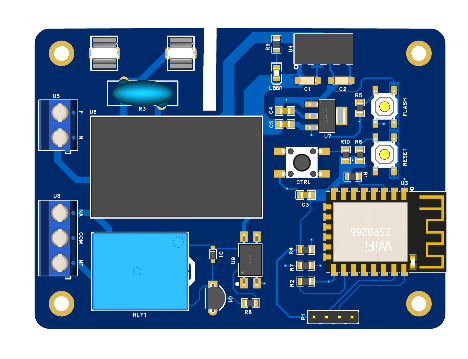
1. ESPHome
- Description: A framework for ESP8266/ESP32-based devices that integrates seamlessly with Home Assistant.
- Features: Supports sensors, relays, LEDs, and more.
- PCB Examples: Many community-designed PCBs for smart switches, environmental monitors, and motor controllers.
- GitHub: https://github.com/esphome
2. OpenHAB
- Description: A vendor-neutral home automation platform with hardware-agnostic support.
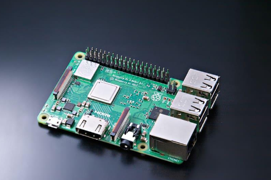
- PCB Integration: Compatible with Raspberry Pi, Arduino, and custom PCBs for sensors/actuators.
- GitHub: https://github.com/openhab
3. Tasmota
- Description: Firmware for ESP devices that enables local control of smart home devices.
- PCB Applications: Used in smart plugs, light controllers, and DIY automation modules.
- GitHub: https://github.com/arendst/Tasmota
4. MySensors
- Description: Open-source framework for wireless IoT and home automation nodes.
- PCB Designs: Includes gateway and sensor node layouts for RF (nRF24L01+) and wired networks.
- GitHub: https://github.com/mysensors
5. Home Assistant Blue
- Description: A custom PCB-based hub designed for Home Assistant, featuring a Raspberry Pi Compute Module.
- Features: Optimized for reliability and local processing.
- GitHub: https://github.com/home-assistant
Designing a PCB for Home Automation
Creating a custom PCB for home automation involves several key steps:
1. Define Requirements
- What functions are needed? (e.g., lighting control, temperature sensing, security)
- Which communication protocol? (Wi-Fi, Zigbee, Z-Wave, Bluetooth, MQTT)
- Power considerations (battery, USB, or mains-powered?)
2. Schematic Design
- Use tools like KiCad, EasyEDA, or Altium Designer.
- Select microcontrollers (e.g., ESP32, STM32, ATmega328P).
- Integrate sensors (DHT22, PIR, ultrasonic) and actuators (relays, servos).
3. PCB Layout
- Optimize for signal integrity and power distribution.
- Ensure proper grounding and noise reduction.
- Consider enclosure compatibility (size, mounting holes).
4. Firmware Development
- Write code in Arduino, MicroPython, or ESP-IDF.
- Implement MQTT/HTTP for cloud-free automation.
- Use OTA (Over-The-Air) updates for remote maintenance.
5. Testing & Deployment
- Prototype on a breadboard before finalizing the PCB.
- Use automated testing (e.g., unit tests for firmware).
- Deploy in stages (e.g., test one room before full integration).
Challenges & Solutions
While DIY PCB home automation is rewarding, challenges include:
| Challenge | Solution |
|---|---|
| RF Interference | Use proper shielding and grounded traces. |
| Power Efficiency | Implement sleep modes for battery-operated devices. |
| Security Risks | Use TLS/SSL for communication, disable default passwords. |
| Component Sourcing | Design with widely available parts (e.g., JLCPCB-compatible). |
| Firmware Bugs | Adopt CI/CD (Continuous Integration) for automated testing. |
Contributing to Open-Source Home Automation
The open-source community thrives on collaboration. Ways to contribute:
- Share Your Designs: Upload PCB Gerber files and schematics to GitHub or platforms like OSHWA.
- Improve Documentation: Help others by writing guides or troubleshooting tips.
- Report & Fix Bugs: Engage in GitHub issue tracking.
- Develop Plugins: Extend functionality (e.g., new sensor drivers for ESPHome).
Conclusion
PCB-based home automation offers a flexible, cost-effective, and secure alternative to commercial smart home systems. Open-source projects like ESPHome, Tasmota, and MySensors provide excellent starting points for DIY enthusiasts. By designing custom PCBs, individuals can tailor automation to their exact needs while contributing to a growing ecosystem of shared knowledge.
Whether you’re a beginner or an experienced engineer, the world of open-source home automation welcomes innovation. Start small—perhaps with a smart light controller—and gradually expand to a fully automated home powered by your own PCBs!


