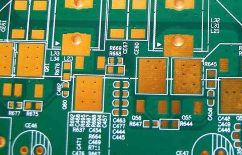
Pcb in transformers
Design Considerations for PCBs in Transformer Applications
When designing printed circuit boards (PCBs) for transformer applications, several critical considerations must be taken into account to ensure optimal performance, reliability, and safety. The integration of PCBs in transformers necessitates a thorough understanding of both electrical and thermal dynamics, as well as the mechanical constraints imposed by the application environment.
To begin with, the selection of materials for the PCB is paramount.
High-frequency transformers, for instance, require substrates with low dielectric losses to minimize energy dissipation. FR-4, a commonly used material, may not always be suitable for high-frequency applications, prompting the need for alternatives such as polyimide or PTFE-based laminates.
Moreover, the layout of the PCB plays a crucial role in mitigating electromagnetic interference (EMI) and ensuring efficient power transfer.
Careful placement of components and routing of traces can significantly reduce parasitic inductance and capacitance, which are detrimental to the transformer’s performance. Utilizing ground planes and proper shielding techniques can further enhance EMI suppression. Additionally, the trace width and spacing must be meticulously calculated to handle the current loads without excessive heating, which could lead to thermal degradation of the PCB and surrounding components.
Thermal management is another critical aspect that cannot be overlooked.
Transformers inherently generate heat during operation, and the PCB must be designed to dissipate this heat effectively. Incorporating thermal vias, heat sinks, and appropriate copper thickness can aid in maintaining the temperature within safe limits. Furthermore, the use of thermal interface materials (TIMs) can improve heat transfer from the PCB to the heat sink, thereby enhancing the overall thermal performance.
Mechanical stability is equally important in transformer applications.
The PCB must withstand mechanical stresses such as vibrations and shocks, which are common in industrial environments. Ensuring robust solder joints and using mechanical fasteners can enhance the durability of the PCB assembly. Additionally, conformal coatings may be applied to protect the PCB from moisture, dust, and other environmental contaminants, thereby extending its operational lifespan.
Another vital consideration is the electrical insulation between different sections of the PCB.
Transformers often operate at high voltages, necessitating adequate insulation to prevent arcing and short circuits. The use of isolation slots, increased creepage and clearance distances, and high-voltage-rated materials can help achieve the required insulation levels. Furthermore, compliance with industry standards and regulations, such as IPC-2221 for PCB design and IEC 60950 for safety, ensures that the design meets the necessary safety and performance criteria.
In addition to these technical considerations, manufacturability and cost-effectiveness must also be taken into account.
Design for manufacturability (DFM) principles should be applied to ensure that the PCB can be produced efficiently and at a reasonable cost. This includes optimizing the design for automated assembly processes, minimizing the number of layers, and selecting components that are readily available and cost-effective.
In conclusion, designing PCBs for transformer applications involves a multifaceted approach that addresses electrical, thermal, mechanical, and safety considerations. By carefully selecting materials, optimizing the layout, managing thermal performance, ensuring mechanical stability, and adhering to insulation requirements, designers can create PCBs that enhance the performance and reliability of transformers. Additionally, considering manufacturability and cost-effectiveness ensures that the design is not only technically sound but also economically viable. Through meticulous planning and attention to detail, the integration of PCBs in transformer applications can be successfully achieved, leading to improved efficiency and longevity of the final product.
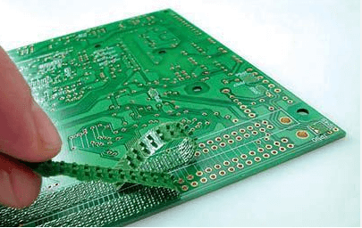
Thermal Management Techniques for Transformer PCBs
Thermal management is a critical aspect of transformer PCB design, as it directly impacts the performance, reliability, and longevity of the device. Effective thermal management techniques are essential to dissipate the heat generated during operation and to maintain the temperature within safe limits. One of the primary methods employed in thermal management is the use of heat sinks. Heat sinks are designed to increase the surface area available for heat dissipation, thereby enhancing the cooling process. They are typically made of materials with high thermal conductivity, such as aluminum or copper, which facilitate the efficient transfer of heat away from the PCB components.
Another important technique involves the use of thermal vias.
These are small, plated holes in the PCB that provide a direct thermal path from the heat-generating components to the other side of the board or to an internal layer. By creating a more efficient heat transfer route, thermal vias help to distribute the heat more evenly across the PCB, reducing the risk of localized hotspots that could damage sensitive components.
In addition to these methods, thermal interface materials (TIMs) play a crucial role in enhancing thermal management.
TIMs are used to fill the microscopic air gaps between the heat-generating components and the heat sinks or other cooling solutions. These materials, which can be in the form of thermal pads, pastes, or adhesives, improve the thermal contact and reduce the thermal resistance, thereby facilitating better heat transfer.
Furthermore, the layout and design of the PCB itself can significantly influence thermal management.
For instance, placing high-power components in areas with better airflow or closer to heat sinks can help in more effective heat dissipation. Additionally, designing the PCB with thicker copper layers can improve its ability to conduct heat away from critical areas. The use of thermal relief patterns in the copper planes can also aid in managing the heat distribution more effectively.
Active cooling solutions, such as fans or liquid cooling systems, can be employed in scenarios where passive cooling methods are insufficient.
Fans can increase the airflow over the PCB, enhancing the convective heat transfer, while liquid cooling systems can provide more efficient heat removal for high-power applications. However, these solutions come with additional complexity and cost, and their implementation needs to be carefully considered based on the specific requirements of the transformer PCB.
Moreover, thermal simulation and analysis tools are invaluable in the design phase.
These tools allow engineers to model the thermal behavior of the PCB and identify potential problem areas before the physical prototype is built. By simulating different thermal management strategies, designers can optimize the PCB layout and cooling solutions to achieve the best thermal performance.
In conclusion, effective thermal management is essential for ensuring the reliable operation of transformer PCBs. By employing a combination of heat sinks, thermal vias, thermal interface materials, strategic PCB design, and, when necessary, active cooling solutions, engineers can manage the heat generated during operation and maintain the temperature within safe limits. Additionally, leveraging thermal simulation tools during the design phase can help in optimizing these techniques, leading to more efficient and reliable transformer PCBs.
Material Selection for High-Performance Transformer PCBs
When designing high-performance transformer printed circuit boards (PCBs), the selection of materials is a critical factor that significantly influences the overall efficiency, reliability, and longevity of the transformer. The choice of materials must account for various electrical, thermal, and mechanical properties to ensure optimal performance under diverse operating conditions. Consequently, understanding the key material properties and their impact on transformer PCB performance is essential for engineers and designers.
One of the primary considerations in material selection for transformer PCBs is the dielectric constant (Dk) of the substrate material.
The dielectric constant affects the signal integrity and impedance of the PCB, which are crucial for maintaining efficient energy transfer and minimizing losses. Materials with a stable and low dielectric constant, such as polytetrafluoroethylene (PTFE) and certain ceramic-filled composites, are often preferred for high-frequency applications. These materials help to reduce signal attenuation and ensure consistent performance across a wide range of frequencies.
In addition to the dielectric constant, the thermal conductivity of the substrate material is another vital factor.
Transformers generate significant amounts of heat during operation, and effective thermal management is necessary to prevent overheating and potential failure. High thermal conductivity materials, such as metal-core PCBs or substrates with embedded thermal vias, facilitate efficient heat dissipation. This ensures that the transformer operates within safe temperature limits, thereby enhancing its reliability and extending its service life.
Mechanical properties, including tensile strength and flexibility, also play a crucial role in material selection for transformer PCBs.
The PCB must withstand mechanical stresses during manufacturing, assembly, and operation without cracking or delaminating. Materials like FR-4, a glass-reinforced epoxy laminate, offer a good balance of mechanical strength and flexibility, making them suitable for a wide range of applications. However, for more demanding environments, advanced materials such as polyimide or high-temperature laminates may be required to ensure durability and performance.
Furthermore, the coefficient of thermal expansion (CTE) of the substrate material must be compatible with the components mounted on the PCB.
A mismatch in CTE can lead to mechanical stress and potential failure of solder joints or other critical connections. Materials with a low and stable CTE, such as certain ceramic-filled composites, help to minimize these risks and ensure reliable operation over a wide temperature range.
Another important consideration is the material’s resistance to environmental factors, such as moisture, chemicals, and radiation.
Transformers often operate in harsh environments, and the PCB materials must be able to withstand these conditions without degrading. Materials with high moisture resistance, such as PTFE or certain high-performance thermoplastics, are ideal for applications where exposure to humidity or water is a concern. Additionally, materials with good chemical resistance and radiation stability are essential for applications in industrial or aerospace environments.
In conclusion, the selection of materials for high-performance transformer PCBs involves a careful evaluation of various electrical, thermal, and mechanical properties. By choosing materials with the appropriate dielectric constant, thermal conductivity, mechanical strength, CTE compatibility, and environmental resistance, engineers can design transformer PCBs that deliver reliable and efficient performance under a wide range of operating conditions. This meticulous approach to material selection not only enhances the performance and longevity of the transformer but also ensures its safe and reliable operation in demanding applications.
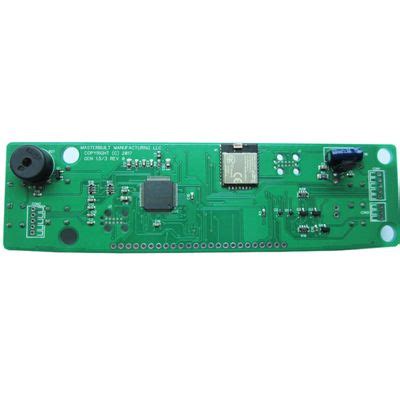
Common Failures and Troubleshooting in Transformer PCBs
Printed Circuit Boards (PCBs) in transformers are critical components that ensure the efficient operation of these electrical devices. However, like any other electronic component, transformer PCBs are susceptible to various failures that can compromise their functionality. Understanding common failures and effective troubleshooting methods is essential for maintaining the reliability and longevity of transformers.
One of the most prevalent issues in transformer PCBs is thermal stress.
Transformers operate under high temperatures, which can cause the PCB materials to expand and contract. Over time, this thermal cycling can lead to the development of micro-cracks in the solder joints and traces. These micro-cracks can disrupt the electrical continuity, leading to intermittent or complete failure of the transformer. To mitigate this issue, it is crucial to use PCBs made from high-temperature-resistant materials and ensure proper thermal management within the transformer housing.
Another common failure mode is related to electrical overstress (EOS).
This can occur due to voltage spikes, surges, or other transient events that exceed the PCB’s voltage rating. EOS can cause immediate damage to the PCB components, such as burnt traces or damaged integrated circuits. To prevent EOS, it is advisable to incorporate protective components like transient voltage suppression (TVS) diodes and varistors into the PCB design. Additionally, ensuring that the transformer operates within its specified voltage range can help minimize the risk of electrical overstress.
Moisture ingress is another significant concern for transformer PCBs.
Exposure to moisture can lead to corrosion of the PCB traces and components, resulting in short circuits or open circuits. This is particularly problematic in environments with high humidity or where the transformer is exposed to water. To address this issue, PCBs can be coated with conformal coatings that provide a protective barrier against moisture. Furthermore, ensuring that the transformer enclosure is properly sealed can help prevent moisture ingress.
Component aging is an inevitable factor that can lead to PCB failures in transformers.
Over time, the performance of electronic components can degrade due to factors such as thermal cycling, electrical stress, and environmental conditions. Capacitors, for instance, can lose their capacitance, and resistors can drift from their specified resistance values. Regular maintenance and periodic testing of the transformer can help identify aging components before they fail. Replacing these components proactively can extend the life of the transformer and prevent unexpected downtime.
In addition to these common failure modes, manufacturing defects can also contribute to PCB failures in transformers.
Poor soldering, misaligned components, and inadequate quality control during the manufacturing process can result in latent defects that manifest over time. To minimize the risk of manufacturing defects, it is essential to work with reputable PCB manufacturers who adhere to stringent quality control standards. Implementing thorough inspection and testing procedures during the production process can also help identify and rectify defects before the PCBs are installed in transformers.
When troubleshooting transformer PCB failures, a systematic approach is essential.
Begin by visually inspecting the PCB for obvious signs of damage, such as burnt components or cracked traces. Using diagnostic tools like multimeters and oscilloscopes can help identify electrical faults and pinpoint the affected areas. In some cases, thermal imaging cameras can be used to detect hotspots that indicate overheating components. Once the root cause of the failure is identified, appropriate corrective actions, such as replacing damaged components or improving thermal management, can be implemented.
In conclusion, transformer PCBs are prone to various failures, including thermal stress, electrical overstress, moisture ingress, component aging, and manufacturing defects. By understanding these common failure modes and employing effective troubleshooting techniques, it is possible to maintain the reliability and performance of transformer PCBs. Regular maintenance, proactive component replacement, and adherence to quality control standards are key strategies for ensuring the longevity of these critical components.

