Pcb on aluminum
PCBs (Printed Circuit Boards) can be mounted on aluminum substrates for various reasons such as better heat dissipation,
improved mechanical stability, and reduced weight.

Aluminum substrates are commonly used in high-power LED applications, power electronics, and automotive electronics.
To mount a PCB on an aluminum substrate, the following steps are typically followed:
1. Choose the appropriate aluminum substrate based on the application requirements such as size, thickness, and thermal conductivity.
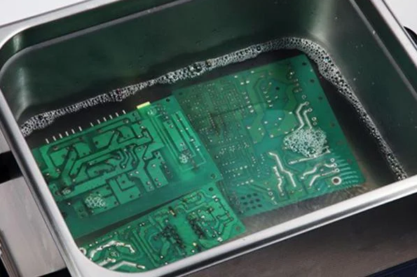
2. Prepare the aluminum substrate by cleaning it thoroughly to remove any dirt, grease, or oxide layers. This can be done using solvents, mechanical cleaning, or chemical etching.
3. Apply a layer of thermal interface material (TIM) on the aluminum substrate to improve heat transfer between the PCB and the substrate. TIMs can be in the form of thermal pads, thermal tapes, or thermal greases.
4. Mount the PCB on the aluminum substrate using screws, clips, or adhesives. The mounting method should ensure good mechanical stability and electrical connectivity between the PCB and the substrate.
5. Connect the PCB to the external components such as power supplies, sensors, and actuators using wires, connectors, or soldering.
6. Test the assembled system to ensure proper functionality and performance.
Overall, mounting a PCB on an aluminum substrate requires careful consideration of the application requirements, material properties, and assembly methods to achieve optimal performance and reliability.

the role of pcb on aluminum
PCBs (Printed Circuit Boards) play a crucial role in the functioning of aluminum-based electronic devices.
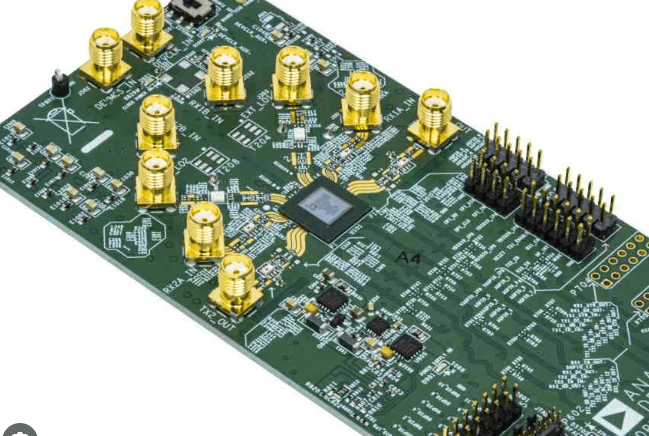
They are used to connect various electronic components such as resistors, capacitors, diodes, and transistors to create a functional circuit.
The PCB acts as a platform for mounting and interconnecting these components, providing a stable and reliable connection between them.
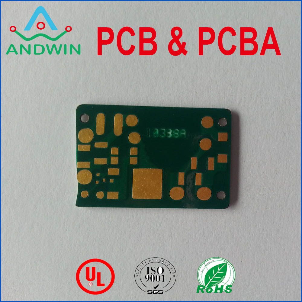
In aluminum-based electronic devices, PCBs are typically made using a layer of copper that is etched to create a circuit pattern.
The copper layer is then laminated onto a substrate material, such as fiberglass or ceramic,
to create a rigid board. The aluminum components are then mounted onto the board and connected to the circuit using solder.

The PCB also plays a critical role in protecting the aluminum components from damage due to environmental factors such as moisture, dust, and heat.
The PCB provides a protective layer that shields the components from these elements, ensuring their longevity and reliability.
In summary, the role of PCBs in aluminum-based electronic devices is to provide a stable and reliable platform for mounting and interconnecting electronic components,
while also protecting them from environmental factors that can cause damage.