Pcb repair
Common Mistakes To Avoid In PCB Repair
Printed Circuit Board (PCB) repair is a critical skill in the electronics industry, requiring precision, knowledge, and attention to detail. However, even experienced technicians can make mistakes that compromise the integrity of the repair. Understanding common pitfalls and how to avoid them is essential for ensuring successful outcomes.
One frequent mistake in PCB repair is neglecting to properly diagnose the issue before attempting a fix.
Rushing into repairs without a thorough understanding of the problem can lead to further damage. It is crucial to use diagnostic tools such as multimeters, oscilloscopes, and thermal cameras to accurately identify faults. This step ensures that the repair addresses the root cause rather than just the symptoms.
Another common error is using inappropriate tools or materials.
For instance, using a soldering iron with an incorrect temperature setting can damage sensitive components or the PCB itself. It is important to use temperature-controlled soldering stations and to select the right type of solder and flux for the specific repair. Additionally, using low-quality replacement parts can result in unreliable repairs. Always source components from reputable suppliers to maintain the integrity of the PCB.
Improper handling of the PCB is another area where mistakes often occur.
Electrostatic discharge (ESD) can easily damage electronic components, so it is vital to use ESD-safe workstations and wear anti-static wrist straps. Furthermore, physical handling should be done with care to avoid bending or flexing the board, which can cause microcracks or break traces. Ensuring a clean and organized workspace can also prevent accidental damage and contamination.
Inadequate cleaning of the PCB before and after repair is a mistake that can lead to long-term reliability issues.
Residual flux, dust, and other contaminants can cause short circuits or corrosion over time. It is essential to clean the board thoroughly using appropriate solvents and brushes. Post-repair inspection under magnification can help identify any remaining contaminants or solder bridges that need to be addressed.
Another significant mistake is failing to follow proper rework procedures.
For example, when removing components, it is important to use desoldering tools such as solder wick or desoldering pumps to avoid damaging the pads or traces. When installing new components, ensuring proper alignment and secure solder joints is crucial. Cold solder joints or misaligned components can lead to intermittent connections or complete failure.
Documentation is often overlooked but is a critical aspect of PCB repair.
Keeping detailed records of the repair process, including diagnostic findings, steps taken, and components replaced, can be invaluable for future troubleshooting and quality control. This practice also helps in maintaining consistency and accountability in repair work.
Lastly, overconfidence can be a detrimental mistake in PCB repair.
Even experienced technicians should approach each repair with caution and humility. Continuous learning and staying updated with the latest repair techniques and industry standards are essential for maintaining high-quality repair work.
In conclusion, avoiding common mistakes in PCB repair requires a combination of proper diagnostic procedures, appropriate tools and materials, careful handling, thorough cleaning, adherence to rework procedures, meticulous documentation, and a commitment to continuous improvement. By being mindful of these factors, technicians can enhance the reliability and longevity of their repairs, ultimately contributing to the overall success of their projects.
Essential Tools For Effective PCB Repair
Printed Circuit Board (PCB) repair is a meticulous process that demands precision, skill, and the right set of tools. The effectiveness of any PCB repair endeavor hinges significantly on the quality and appropriateness of the tools employed. To ensure successful outcomes, it is imperative to understand the essential tools required for effective PCB repair and their respective roles in the process.
First and foremost, a high-quality soldering iron is indispensable for any PCB repair task.
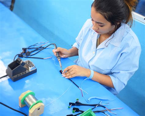
This tool is used to melt solder, allowing components to be securely attached to the board. A soldering iron with adjustable temperature control is particularly beneficial, as different components and solder types require varying temperatures. Coupled with the soldering iron, solder wire is equally crucial. Lead-free solder is often preferred due to its environmental benefits, although it requires higher temperatures to melt compared to leaded solder.
In addition to the soldering iron, a desoldering tool is essential for removing solder from joints and components.
Desoldering pumps, also known as solder suckers, are commonly used for this purpose. They create a vacuum to suck up molten solder, thereby facilitating the removal of components. Alternatively, desoldering braid or wick can be used to absorb solder through capillary action, providing a clean and efficient method for desoldering.
Another critical tool in PCB repair is the multimeter.
This versatile instrument measures electrical properties such as voltage, current, and resistance, enabling the technician to diagnose faults and verify the integrity of connections. A digital multimeter with high accuracy and a wide range of measurement capabilities is particularly advantageous for detailed diagnostics.
Precision is paramount in PCB repair, and this necessitates the use of fine-tipped tweezers.
These tools allow for the careful handling and placement of small components, minimizing the risk of damage. Additionally, magnification tools such as a magnifying glass or a microscope are invaluable for inspecting solder joints and identifying minute defects that may not be visible to the naked eye.
To ensure a clean working environment, an anti-static mat and wrist strap are essential.
These tools prevent the buildup of static electricity, which can damage sensitive electronic components. By grounding the technician and the work surface, these anti-static measures safeguard the integrity of the PCB and its components.
Furthermore, a hot air rework station is a versatile tool that can be used for soldering and desoldering surface-mount components.
By directing a controlled stream of hot air onto the solder joints, this tool allows for the precise removal and replacement of components without direct contact, reducing the risk of damage.
In addition to these primary tools, several ancillary items contribute to effective PCB repair.
Flux, for instance, is used to clean and prepare surfaces for soldering, ensuring strong and reliable joints. Cleaning solvents and brushes are also essential for removing flux residues and other contaminants from the PCB, maintaining its functionality and appearance.
In conclusion, effective PCB repair requires a comprehensive toolkit comprising a soldering iron, desoldering tools, a multimeter, precision tweezers, magnification tools, anti-static measures, and a hot air rework station, among other ancillary items. Each tool plays a vital role in ensuring the precision, reliability, and success of the repair process. By investing in high-quality tools and understanding their proper use, technicians can achieve optimal results in PCB repair, thereby extending the lifespan and performance of electronic devices.
Step-By-Step Guide To Soldering Components On A PCB
Soldering components onto a printed circuit board (PCB) is a fundamental skill in electronics repair and assembly. This process, while intricate, can be mastered with careful attention to detail and adherence to proper techniques. To begin, it is essential to gather all necessary tools and materials, including a soldering iron, solder, flux, tweezers, a desoldering pump or braid, and the components to be soldered. Ensuring a clean and organized workspace is also crucial to avoid any mishaps during the soldering process.
First, it is important to prepare the PCB and components.
Inspect the PCB for any pre-existing damage or debris that could interfere with the soldering process. Clean the board using isopropyl alcohol and a lint-free cloth to remove any contaminants. Similarly, ensure that the components are free from oxidation or dirt, as this can affect the quality of the solder joints.
Next, position the components on the PCB.
This step requires precision, as the components must be placed in their designated locations according to the circuit design. Using tweezers can help in accurately positioning small components. Once the components are in place, it is advisable to secure them temporarily with a small amount of adhesive or by bending the leads slightly to hold them in position.
With the components properly positioned, the next step is to apply flux to the solder pads and component leads.
Flux is a chemical cleaning agent that helps to remove oxidation and improve the flow of solder, resulting in stronger and more reliable joints. Apply a small amount of flux to each pad and lead using a flux pen or brush.
Now, it is time to heat the soldering iron.
Set the temperature of the soldering iron to an appropriate level, typically around 350°C (662°F) for most standard soldering tasks. Allow the iron to reach the desired temperature before proceeding. Once heated, clean the tip of the soldering iron using a damp sponge or brass wire cleaner to remove any oxidation or old solder.
Begin soldering by placing the tip of the soldering iron on the joint where the component lead meets the solder pad.
Hold the iron in place for a few seconds to heat both the pad and the lead. Then, introduce the solder to the joint, allowing it to flow and cover the connection. It is important to use just enough solder to form a concave fillet around the lead without creating a large blob. Remove the soldering iron and allow the joint to cool naturally.
Repeat this process for each component, ensuring that all joints are properly soldered.
If any mistakes are made, such as excess solder or a cold joint, use a desoldering pump or braid to remove the solder and re-solder the joint correctly. After all components are soldered, inspect the board for any solder bridges or shorts that could cause malfunction.
Finally, clean the PCB again to remove any residual flux, which can be corrosive over time.
Use isopropyl alcohol and a brush to thoroughly clean the board, ensuring that all flux residues are removed. Once cleaned, the PCB is ready for testing and use.
By following these steps meticulously, one can achieve high-quality solder joints and ensure the reliable operation of the PCB. Mastery of soldering techniques not only enhances the functionality of electronic devices but also extends their lifespan, making it a valuable skill for any electronics enthusiast or professional.
How To Diagnose And Fix PCB Short Circuits
Printed Circuit Boards (PCBs) are integral components in modern electronic devices, and their proper functioning is crucial for the overall performance of these devices.
One of the most common issues that can arise with PCBs is short circuits.
Diagnosing and fixing PCB short circuits requires a methodical approach, combining both theoretical knowledge and practical skills. Understanding the steps involved in this process can help ensure that the repair is both effective and efficient.
To begin with, diagnosing a PCB short circuit involves identifying the symptoms that indicate a problem.
Common signs include the device not powering on, unexpected behavior, or visible damage such as burnt components. Once these symptoms are observed, the next step is to isolate the short circuit. This can be done using a multimeter, an essential tool for any PCB repair task. By setting the multimeter to the continuity mode, you can check for continuity between different points on the PCB. A continuous beep indicates a short circuit, whereas no beep suggests that the circuit is open.
After identifying the general area of the short circuit, a more detailed inspection is necessary.
This involves visually examining the PCB for any obvious signs of damage, such as burnt traces, solder bridges, or misplaced components. Magnification tools, such as a magnifying glass or a microscope, can be particularly useful in this step, as they allow for a closer inspection of the intricate details of the PCB.
Once the short circuit has been located, the next step is to fix it.
This often involves removing the faulty component or repairing the damaged trace. If a solder bridge is causing the short circuit, desoldering the excess solder using a desoldering pump or solder wick can resolve the issue. In cases where a component is damaged, it must be carefully desoldered and replaced with a new one. It is important to ensure that the replacement component is of the same specification to maintain the integrity of the circuit.
In some instances, the short circuit may be caused by a damaged trace on the PCB.
Repairing a damaged trace involves scraping away the protective solder mask to expose the copper trace, then using a conductive pen or solder to bridge the gap. This process requires precision and a steady hand to avoid causing further damage to the PCB.
After the repair is completed, it is crucial to test the PCB to ensure that the short circuit has been successfully resolved.
This involves rechecking the continuity with a multimeter and powering on the device to observe its behavior. If the device functions as expected, the repair can be considered successful. However, if issues persist, further diagnosis may be necessary to identify any additional problems.
In conclusion, diagnosing and fixing PCB short circuits is a meticulous process that requires a combination of careful observation, precise tools, and technical expertise. By following a systematic approach, it is possible to effectively identify and repair short circuits, thereby restoring the functionality of the electronic device. This not only extends the lifespan of the device but also contributes to more sustainable electronic practices by reducing the need for complete replacements.

