Pcb rf fnb
Design Considerations for PCB RF FNB
Designing printed circuit boards (PCBs) for radio frequency (RF) and front-end network (FNB) applications requires meticulous attention to detail and a deep understanding of both electrical and mechanical principles. The complexity of RF signals, coupled with the need for precise signal integrity, makes the design process particularly challenging. To achieve optimal performance, several key considerations must be taken into account.
Firstly, the choice of materials is paramount.
High-frequency signals are susceptible to losses and interference, which can be mitigated by selecting substrates with low dielectric constants and low loss tangents. Materials such as Rogers or Teflon are often preferred over traditional FR4 due to their superior electrical properties. These materials help maintain signal integrity by minimizing dielectric losses and ensuring consistent impedance throughout the PCB.
Transitioning to the layout, the placement of components is another critical factor.
RF components, such as amplifiers, mixers, and filters, should be strategically positioned to minimize signal path lengths and reduce potential interference. Placing sensitive components away from noisy digital circuits can significantly enhance performance. Additionally, maintaining a consistent ground plane is essential to provide a low-impedance return path for RF signals, thereby reducing electromagnetic interference (EMI) and crosstalk.
Moreover, impedance matching is a crucial aspect of RF PCB design.
Mismatched impedances can lead to signal reflections, which degrade signal quality and reduce overall system efficiency. To address this, designers must carefully calculate and control the impedance of transmission lines. Microstrip and stripline techniques are commonly employed to achieve the desired impedance. These techniques involve precise control of trace width, spacing, and the dielectric properties of the substrate.
In addition to impedance matching, signal integrity must be preserved through proper routing techniques.
Avoiding sharp bends and maintaining consistent trace widths are essential practices. Sharp bends can cause signal reflections and impedance discontinuities, while inconsistent trace widths can lead to variations in impedance. Utilizing curved traces and maintaining uniform trace dimensions can mitigate these issues.
Thermal management is another vital consideration in RF PCB design.
High-frequency components often generate significant heat, which can affect performance and reliability. Effective thermal management strategies, such as the use of thermal vias, heat sinks, and proper airflow, are necessary to dissipate heat and maintain optimal operating temperatures. Ensuring adequate thermal relief for components can prevent overheating and extend the lifespan of the PCB.
Furthermore, shielding and isolation techniques play a crucial role in minimizing EMI and ensuring signal integrity.
Shielding sensitive components and signal traces with grounded metal enclosures or using ground planes can effectively reduce EMI. Additionally, isolating high-frequency circuits from low-frequency or digital circuits can prevent interference and maintain signal clarity.
Lastly, thorough testing and validation are essential to ensure the PCB meets the desired performance criteria.
Simulation tools can be used during the design phase to predict and analyze the behavior of RF signals. Post-fabrication testing, including network analysis and time-domain reflectometry, can verify impedance matching, signal integrity, and overall performance.
In conclusion, designing PCBs for RF FNB applications demands a comprehensive understanding of material properties, component placement, impedance matching, signal routing, thermal management, and EMI mitigation. By carefully considering these factors and employing best practices, designers can create high-performance RF PCBs that meet the stringent requirements of modern communication systems. The intricate balance of these elements underscores the complexity and precision required in RF PCB design, ultimately leading to reliable and efficient front-end network solutions.

Common Challenges in PCB RF FNB Manufacturing
In the realm of electronics manufacturing, the production of Printed Circuit Boards (PCBs) for Radio Frequency (RF) and Fine-Pitch Ball Grid Array (FNB) applications presents a unique set of challenges. These challenges stem from the intricate nature of RF signals and the precise requirements of FNB components, necessitating meticulous attention to detail and advanced manufacturing techniques. Understanding these common challenges is crucial for ensuring the reliability and performance of the final product.
One of the primary challenges in PCB RF FNB manufacturing is signal integrity.
RF signals are highly susceptible to interference and loss, which can significantly impact the performance of the device. To mitigate these issues, manufacturers must carefully design the PCB layout to minimize signal degradation. This involves optimizing trace widths, spacing, and routing paths to reduce impedance mismatches and crosstalk. Additionally, the use of high-quality materials with low dielectric loss is essential to maintain signal integrity over the operating frequency range.
Another significant challenge is thermal management.
RF components often generate substantial heat during operation, which can lead to thermal stress and potential failure if not properly managed. Effective thermal management strategies, such as the incorporation of thermal vias, heat sinks, and appropriate PCB materials, are critical to dissipate heat efficiently. Moreover, precise control of the reflow soldering process is necessary to ensure that FNB components are securely attached without causing thermal damage to the PCB or other components.
The miniaturization of electronic devices has led to the increasing use of FNB components, which require extremely fine pitch connections.
This presents a challenge in terms of manufacturing precision and reliability. The placement and soldering of FNB components demand high accuracy to avoid bridging and ensure proper electrical connections. Advanced pick-and-place machines and soldering techniques, such as laser soldering or precision reflow ovens, are often employed to achieve the required level of precision. Furthermore, thorough inspection and testing are essential to identify and rectify any defects that may arise during the manufacturing process.
Electromagnetic compatibility (EMC) is another critical consideration in PCB RF FNB manufacturing.
RF devices must comply with stringent EMC regulations to prevent interference with other electronic devices. Achieving EMC compliance involves careful design practices, such as the implementation of proper grounding and shielding techniques. Additionally, the use of decoupling capacitors and ferrite beads can help to suppress unwanted noise and ensure stable operation. Manufacturers must also conduct rigorous EMC testing to verify that the PCB meets the required standards.
Material selection plays a pivotal role in addressing the challenges of PCB RF FNB manufacturing.
The choice of substrate material, copper thickness, and surface finish can significantly impact the performance and reliability of the PCB. For RF applications, materials with low dielectric constant and loss tangent are preferred to minimize signal attenuation. In contrast, FNB components require substrates with high dimensional stability and excellent thermal properties to withstand the demands of fine-pitch soldering.
In conclusion, the manufacturing of PCBs for RF and FNB applications involves navigating a complex landscape of challenges. Signal integrity, thermal management, precision in component placement, EMC compliance, and material selection are all critical factors that must be meticulously addressed to ensure the success of the final product. By leveraging advanced manufacturing techniques and adhering to best practices, manufacturers can overcome these challenges and deliver high-performance, reliable PCBs for a wide range of applications.
Advanced Materials for PCB RF FNB Applications
In the realm of modern electronics, the development of advanced materials for printed circuit boards (PCBs) used in radio frequency (RF) and fine-pitch ball grid array (FNB) applications has become increasingly critical. As the demand for higher performance and miniaturization continues to grow, the selection of appropriate materials plays a pivotal role in ensuring the reliability and efficiency of these sophisticated electronic systems. This article delves into the advanced materials that are shaping the future of PCB RF FNB applications, highlighting their unique properties and the benefits they bring to the table.
To begin with, the primary consideration in selecting materials for PCB RF FNB applications is their dielectric properties
. Dielectric constant (Dk) and dissipation factor (Df) are two crucial parameters that influence signal integrity and loss. Materials with a low dielectric constant and low dissipation factor are preferred as they minimize signal delay and power loss, which are essential for high-frequency applications. Polytetrafluoroethylene (PTFE) composites, for instance, are widely used due to their excellent dielectric properties and low loss characteristics. These materials are particularly suitable for RF applications where signal integrity is paramount.
Moreover, thermal management is another critical aspect that cannot be overlooked.
As electronic devices become more compact and powerful, the heat generated during operation can significantly impact performance and longevity. Advanced materials with high thermal conductivity, such as ceramic-filled PTFE and metal-backed laminates, are increasingly being utilized to dissipate heat effectively. These materials not only enhance thermal performance but also contribute to the overall mechanical stability of the PCB, ensuring that the components remain securely in place even under thermal stress.
In addition to dielectric and thermal properties, the mechanical robustness of the materials is equally important.
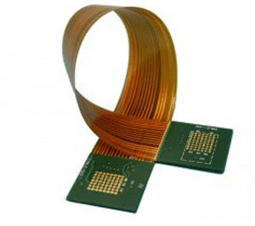
The miniaturization trend in electronics has led to the widespread adoption of fine-pitch ball grid arrays (FNB), which require materials that can withstand the mechanical stresses associated with assembly and operation. High-performance laminates with enhanced mechanical strength and flexibility, such as liquid crystal polymer (LCP) and polyimide, are gaining traction in this domain. These materials offer excellent dimensional stability and resistance to environmental factors, making them ideal for FNB applications.
Furthermore, the advent of high-speed digital and RF applications has necessitated the use of materials with superior signal transmission capabilities.
Low-loss materials, such as hydrocarbon ceramic laminates, are being increasingly employed to meet the stringent requirements of high-frequency signal transmission. These materials exhibit low insertion loss and high signal integrity, which are crucial for maintaining the performance of high-speed digital circuits and RF components.
Transitioning to the manufacturing aspect, the compatibility of advanced materials with existing fabrication processes is a key consideration.
Materials that can be easily integrated into standard PCB manufacturing workflows without requiring significant modifications are highly desirable. This ensures that the benefits of advanced materials can be realized without incurring excessive costs or delays in production. For instance, the use of modified epoxy resins that offer improved thermal and electrical properties while being compatible with conventional PCB fabrication techniques is a notable advancement in this regard.
In conclusion, the development and adoption of advanced materials for PCB RF FNB applications are driving significant advancements in the electronics industry. By offering superior dielectric properties, enhanced thermal management, mechanical robustness, and excellent signal transmission capabilities, these materials are enabling the creation of high-performance, reliable, and miniaturized electronic systems. As technology continues to evolve, the ongoing research and innovation in advanced materials will undoubtedly play a crucial role in meeting the ever-increasing demands of modern electronic applications.
Testing and Validation Techniques for PCB RF FNB
Testing and validation techniques for PCB RF FNB are critical to ensuring the reliability and performance of radio frequency (RF) front-end boards (FNB) in various applications. These techniques encompass a range of methodologies designed to evaluate the electrical characteristics, signal integrity, and overall functionality of the PCB RF FNB. To begin with, one of the primary methods employed in testing PCB RF FNB is the use of vector network analyzers (VNAs). VNAs are instrumental in measuring the scattering parameters (S-parameters) of the RF circuits, which provide valuable insights into the reflection and transmission properties of the board. By analyzing these parameters, engineers can identify impedance mismatches, signal losses, and other anomalies that may affect the performance of the RF front-end.
In addition to VNAs, time-domain reflectometry (TDR) is another essential technique used in the validation process.
TDR involves sending a fast-rise-time pulse through the PCB trace and observing the reflected signals. This method is particularly useful for detecting discontinuities, such as open circuits, short circuits, and impedance variations along the transmission lines. By pinpointing these issues, engineers can make necessary adjustments to the PCB design to enhance signal integrity.
Moreover, spectrum analyzers play a crucial role in the testing of PCB RF FNB.
These devices measure the frequency spectrum of the RF signals, allowing engineers to assess the harmonic content, spurious emissions, and overall spectral purity. Ensuring that the RF front-end operates within the specified frequency range and adheres to regulatory standards is vital for preventing interference with other electronic devices and communication systems.
Transitioning to another important aspect, power measurement techniques are also integral to the validation of PCB RF FNB.
Power meters and sensors are used to measure the output power of the RF signals, ensuring that the board delivers the required power levels for optimal performance. Accurate power measurements are essential for applications such as wireless communication, where signal strength directly impacts the quality of the transmission.
Furthermore, thermal testing is a critical component of the validation process.
RF front-end boards often operate at high frequencies, generating significant amounts of heat. Thermal cameras and infrared sensors are employed to monitor the temperature distribution across the PCB. Identifying hotspots and ensuring effective thermal management is crucial for preventing overheating and ensuring the longevity of the board.
Additionally, electromagnetic compatibility (EMC) testing is essential to ensure that the PCB RF FNB does not emit or succumb to unwanted electromagnetic interference (EMI).
EMC testing involves subjecting the board to various electromagnetic environments and measuring its susceptibility and emissions. Compliance with EMC standards is necessary to guarantee that the RF front-end can coexist with other electronic systems without causing or experiencing interference.
Lastly, automated testing systems (ATS) are increasingly being utilized to streamline the validation process.
ATS can perform a series of predefined tests on the PCB RF FNB, significantly reducing the time and effort required for manual testing. These systems can execute complex test sequences, record data, and generate comprehensive reports, providing engineers with a detailed overview of the board’s performance.
In conclusion, the testing and validation of PCB RF FNB involve a multifaceted approach that includes vector network analysis, time-domain reflectometry, spectrum analysis, power measurement, thermal testing, electromagnetic compatibility testing, and automated testing systems. Each technique plays a vital role in ensuring that the RF front-end board meets the required specifications and performs reliably in its intended application. By employing these rigorous testing methodologies, engineers can identify and rectify potential issues, ultimately delivering high-quality RF front-end boards that meet industry standards and customer expectations.

