PCB Short Circuit Analysis: Causes, Detection, and Prevention
Introduction
Printed Circuit Boards (PCBs) are the backbone of modern electronics, enabling the interconnection of various components to form functional circuits. However, one of the most common and critical issues affecting PCBs is short circuits. A short circuit occurs when an unintended low-resistance path forms between two or more conductive elements, leading to excessive current flow, overheating, and potential device failure.
This article explores the causes, detection methods, and prevention strategies for PCB short circuits. By understanding these aspects, engineers and manufacturers can improve PCB reliability and performance.
1. Causes of PCB Short Circuits
Short circuits in PCBs can arise from multiple factors, including design flaws, manufacturing defects, and environmental conditions. The primary causes include:
1.1 Design-Related Causes
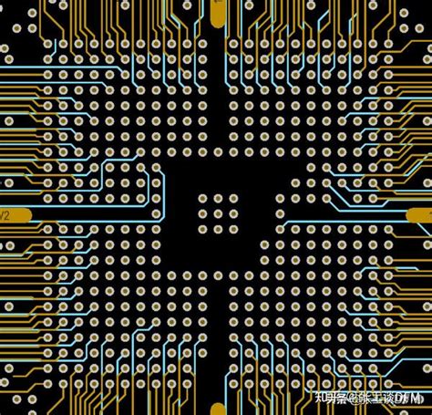
- Insufficient Clearance and Creepage Distance:
- If conductive traces or pads are placed too close together, voltage differences can cause arcing or unintended connections.
- High-voltage PCBs require strict adherence to clearance rules to prevent shorting.
- Improper Via Placement:
- Vias that are too close to traces or other vias can create short circuits due to solder bridging or plating defects.
- Incorrect Net Assignments:
- Errors in schematic design or netlist generation may lead to unintended connections between power and ground.
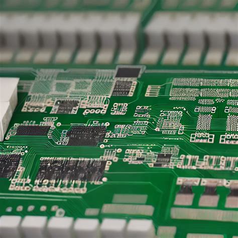
1.2 Manufacturing Defects
- Solder Bridging:
- Excess solder during assembly can create unintended connections between adjacent pins or traces.
- Copper Residuals (Etching Issues):
- Incomplete etching during PCB fabrication can leave conductive copper strands, causing shorts between traces.
- Plating Problems in Vias and PTHs (Plated Through-Holes):
- Poor plating can lead to voids or cracks, causing intermittent or permanent shorts.
- Component Misalignment:
- Misplaced components (e.g., capacitors or resistors) can create unintended contact between pins.
1.3 Environmental and Operational Factors
- Contamination (Dust, Moisture, Flux Residue):
- Conductive debris or moisture can create leakage paths between traces.
- Mechanical Stress:
- Flexing or impact can crack solder joints or PCB layers, leading to short circuits.
- Thermal Cycling:
- Repeated heating and cooling can weaken solder joints, increasing the risk of shorts.
2. Detection Methods for PCB Short Circuits
Identifying short circuits early is crucial to preventing catastrophic failures. Several techniques are employed for detection:
2.1 Visual Inspection
- Microscopic Examination:
- High-magnification tools help detect solder bridges, copper residues, and damaged traces.
- Automated Optical Inspection (AOI):
- Cameras and AI algorithms scan PCBs for manufacturing defects.
2.2 Electrical Testing
- Continuity Testing (Multimeter):
- A basic method to check for unintended connections between power and ground.
- In-Circuit Testing (ICT):
- Bed-of-nails testers verify electrical connectivity and isolate shorts.
- Time-Domain Reflectometry (TDR):
- Detects impedance mismatches caused by shorts in high-speed PCBs.
2.3 Thermal Imaging
- Infrared Cameras:
- Short circuits generate heat, which can be visualized using thermal imaging.
2.4 X-Ray Inspection
- Non-Destructive Testing:
- Reveals hidden defects in multilayer PCBs, such as via cracks or internal shorts.
2.5 Advanced Techniques
- Scanning Acoustic Microscopy (SAM):
- Uses ultrasound to detect delamination and internal defects.
- Current Tracing with Liquid Crystal Film:
- Highlights current paths to locate shorts.

3. Prevention and Mitigation Strategies
Preventing short circuits requires a combination of robust design practices, quality manufacturing, and thorough testing.
3.1 Design Best Practices
- Maintain Proper Clearance and Creepage:
- Follow IPC-2221 standards for trace spacing based on voltage levels.
- Use DFM (Design for Manufacturing) Guidelines:
- Avoid sharp angles in traces, ensure proper solder mask coverage, and optimize via placement.
- Implement Test Points for Debugging:
- Include accessible test points for probing during troubleshooting.
3.2 Manufacturing Quality Control
- Automated Optical Inspection (AOI):
- Ensures solder joints and traces meet specifications.
- Electrical Testing (Flying Probe, ICT):
- Validates PCB functionality before deployment.
- Controlled Soldering Processes:
- Use solder paste inspection (SPI) to prevent bridging.
3.3 Environmental Protection
- Conformal Coating:
- Protects PCBs from moisture, dust, and chemical exposure.
- Proper Storage Conditions:
- Store PCBs in anti-static and humidity-controlled environments.
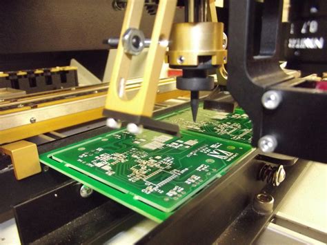
3.4 Repair and Rework Techniques
- Solder Wick or Hot Air Rework:
- Removes excess solder causing bridges.
- Trace Repair Kits:
- Fixes broken or shorted traces with conductive epoxy or jumper wires.
4. Case Study: Real-World PCB Short Circuit Analysis
Scenario: A batch of industrial control PCBs exhibited intermittent failures.
Investigation Steps:
- Initial Testing: Multimeter detected a short between 3.3V and GND.
- Thermal Imaging: Revealed a hotspot near a decoupling capacitor.
- X-Ray Inspection: Discovered a solder ball inside a via, creating an intermittent short.
Solution:
- The manufacturing process was revised to include better solder paste stencil cleaning.
- Additional AOI checks were implemented to catch similar defects early.
5. Conclusion
PCB short circuits are a significant reliability concern but can be effectively managed through proper design, manufacturing controls, and testing. By understanding the root causes, employing advanced detection methods, and adhering to best practices, engineers can minimize the risk of short circuits and enhance PCB performance.
As PCBs continue to evolve with higher densities and faster signals, the importance of thorough short circuit analysis will only grow. Investing in prevention and early detection ultimately leads to more robust and dependable electronic systems.