PCB Solder Joint Failure Mechanisms: An In-Depth Analysis of Poor Solder Wetting Phenomena
Abstract
This paper examines the underlying failure mechanisms behind poor solder wetting phenomena in printed circuit board (PCB) assembly processes. With the continuous miniaturization of electronic components and increasing complexity of PCB designs, solder joint reliability has become critical for product quality. The article systematically analyzes various factors contributing to solder wetting failures, including metallurgical interactions, surface contamination, thermal profile issues, and material incompatibilities. By understanding these root causes, manufacturers can implement effective countermeasures to improve soldering quality and product reliability.
1. Introduction
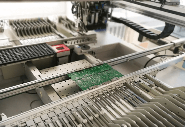
Solder joint formation is a critical process in PCB assembly that directly affects the electrical conductivity and mechanical stability of electronic connections. Poor solder wetting, manifested as incomplete adhesion between solder and pad or component lead, represents one of the most common soldering defects in surface mount technology (SMT) and through-hole assembly. Industry surveys indicate that solder-related defects account for approximately 30-40% of all PCB manufacturing failures, with poor wetting being a predominant issue.
This paper investigates the multifaceted nature of solder wetting failures by examining the fundamental physical and chemical processes involved in solder joint formation. The analysis covers both lead-based (SnPb) and lead-free (primarily SAC alloys) soldering systems, highlighting differences in their wetting behaviors.
2. Fundamentals of Solder Wetting
2.1 Thermodynamics of Solder Wetting
Solder wetting is governed by surface energy relationships described by Young’s equation:
γsv = γsl + γlvcosθ
Where:
- γsv = surface energy at the solid-vapor interface
- γsl = surface energy at the solder-substrate interface
- γlv = surface tension of liquid solder
- θ = contact angle
Good wetting occurs when θ < 90°, while poor wetting shows θ > 90°. The contact angle depends on the balance between adhesive forces (solder to substrate) and cohesive forces (within solder).
2.2 Stages of Solder Joint Formation
- Flux Activation: Removal of oxides and surface contaminants
- Thermal Equilibrium: Substrate reaches soldering temperature
- Intermetallic Formation: Metallurgical bonding between solder and substrate
- Solidification: Controlled cooling to form reliable joint
Failure at any stage can lead to wetting defects.
3. Primary Mechanisms Behind Poor Solder Wetting
3.1 Surface Contamination and Oxidation
Copper Pad Oxidation:
- Exposure to air forms Cu2O and CuO layers (1-10nm thick)
- Critical thickness: >3nm significantly impairs wetting
- Accelerated by humidity and elevated temperatures
Organic Contamination:
- Fingerprints, oils, mold release agents
- Solder mask residues
- Cleaning solvent residues
Sulfide Formation:
- Reaction with sulfur-containing air pollutants
- Forms Cu2S which is difficult for flux to remove
3.2 Inadequate Thermal Profiles
Insufficient Preheat:
- Incomplete flux activation
- Thermal shock causing component damage
- Typical requirement: 150-180°C for 60-90 seconds
Peak Temperature Issues:
- Too low: Incomplete solder melting (especially problematic for lead-free alloys)
- Too high: Excessive intermetallic growth, flux burnout
- SAC305 requires 240-250°C peak temperature
Time Above Liquidus (TAL):
- Insufficient TAL: Incomplete wetting
- Excessive TAL: Thick intermetallic layers
- Optimal range: 30-90 seconds
3.3 Flux-Related Problems
Flux Activity:
- Rosin (RA), no-clean, and water-soluble fluxes have different activation levels
- Inappropriate selection for surface conditions
Flux Depletion:
- Excessive time between paste printing and reflow
- Volatile component evaporation
Flux Residues:
- Carbonized flux can create wetting barriers
- Particularly problematic with no-clean fluxes at high temperatures
3.4 Metallurgical Factors
Intermetallic Compound (IMC) Formation:
- Cu6Sn5 (η-phase) forms first during wetting
- Cu3Sn (ε-phase) forms at Cu/η-phase interface
- Optimal IMC thickness: 1-5μm
- Excessive IMC growth leads to brittle joints
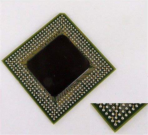
Dissolution of Surface Finishes:
- Excessive dissolution of ENIG (Electroless Nickel Immersion Gold) or HASL coatings
- Nickel diffusion barriers in ENIG can be compromised
Kirkendall Voiding:
- Unequal diffusion rates of Cu and Sn
- Creates porosity at Cu3Sn interface
- Aggravated by multiple reflow cycles
3.5 Solder Material Issues
Oxidized Solder Powder:
- In solder paste formulations
- Increases viscosity and reduces flowability
Alloy Segregation:
- Compositional inhomogeneity
- Particularly affects lead-free alloys with multiple components
Solder Aging:
- Metal powder oxidation in solder paste
- Typically 6-12 month shelf life at refrigerated temperatures
4. Failure Analysis Techniques
4.1 Visual Inspection
- Low magnification (10-50X) examination of wetting angle
- Solder balling or dewetting patterns
4.2 Cross-Sectional Analysis
- Sample preparation with epoxy mounting and polishing
- SEM/EDS for IMC characterization
4.3 Surface Analysis
- X-ray Photoelectron Spectroscopy (XPS) for surface chemistry
- Auger Electron Spectroscopy (AES) for thin oxide layers
4.4 Thermal Analysis
- Differential Scanning Calorimetry (DSC) for solder melting behavior
- Thermogravimetric Analysis (TGA) for flux characteristics
5. Case Studies
5.1 Black Pad Phenomenon in ENIG
- Hyper-corrosion of nickel-phosphorus layer
- Resulting in poor gold dissolution and nickel oxidation
- Characteristic black appearance under gold layer
5.2 Halide-Induced Corrosion
- Chloride or bromide contamination from handling
- Accelerates copper oxidation during reflow
- Creates localized wetting failures
5.3 Solder Mask Undercut
- Improper solder mask adhesion at pad edges
- Creates crevices for flux entrapment
- Leads to uneven wetting fronts
6. Prevention and Mitigation Strategies
6.1 Process Control Measures
- Strict humidity control (<40% RH) in storage areas
- Nitrogen reflow atmosphere (O2 < 500ppm)
- First-in-first-out (FIFO) material handling
6.2 Design Improvements
- Pad geometry optimization for better thermal balance
- Solder mask design with proper clearance
- Thermal relief patterns for large copper areas
6.3 Material Selection
- High-reliability surface finishes (e.g., ENEPIG instead of ENIG)
- Appropriate flux activity for application
- Fresh solder paste with proper storage
6.4 Process Optimization
- Profile development using solder paste manufacturer guidelines
- Thermocouple placement at critical components
- Regular reflow oven maintenance and calibration
7. Conclusion
Poor solder wetting in PCB assembly results from complex interactions between material properties, process parameters, and environmental conditions. The primary failure mechanisms involve surface contamination, inadequate thermal management, flux chemistry limitations, and metallurgical incompatibilities. Effective prevention requires a holistic approach addressing all stages from design to manufacturing.
Future challenges include adapting to continued miniaturization, higher-density interconnects, and emerging solder alloy formulations. Advanced analytical techniques and real-time process monitoring will become increasingly important for maintaining solder joint reliability in next-generation electronics manufacturing.