PCB Thermal Design Optimization: Strategies and Best Practices
1. Introduction
Printed Circuit Boards (PCBs) are the backbone of modern electronic devices, from consumer electronics to industrial systems. As electronic components become more powerful and compact, managing heat dissipation has become a critical challenge in PCB design. Excessive heat can lead to component failure, reduced performance, and shortened product lifespan. Therefore, optimizing PCB thermal design is essential to ensure reliability, efficiency, and longevity.
This article explores key strategies for PCB thermal design optimization, including material selection, layout techniques, thermal vias, heat sinks, and simulation tools. By implementing these best practices, engineers can enhance thermal performance and prevent overheating issues.
2. Importance of Thermal Management in PCBs
Heat is generated in PCBs due to power dissipation in active components such as CPUs, GPUs, power transistors, and voltage regulators. Poor thermal management can result in:
- Component degradation (e.g., solder joint failure, delamination).
- Reduced electrical performance (e.g., increased resistance, signal integrity issues).
- Thermal runaway in power electronics, leading to catastrophic failure.
Effective thermal design ensures:
- Improved reliability (longer operational life).
- Better performance (stable operation under high loads).
- Compliance with safety standards (e.g., IPC, UL).
3. Key Factors Affecting PCB Thermal Performance
3.1 PCB Material Selection
The choice of substrate material significantly impacts thermal conductivity. Common PCB materials include:
- FR-4: Standard material with low thermal conductivity (~0.3 W/mK).
- Metal-Core PCBs (MCPCBs): Use aluminum or copper cores for better heat dissipation (5-400 W/mK).
- Ceramic Substrates (e.g., Alumina, Aluminum Nitride): High thermal conductivity (24-170 W/mK) for high-power applications.
- High-Tg (Glass Transition Temperature) Materials: Better thermal stability for high-temperature environments.
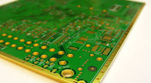
3.2 Copper Thickness and Traces
- Thicker copper layers (2 oz or more) improve heat spreading.
- Wider power traces reduce resistance and heat generation.
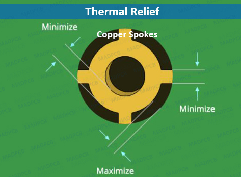
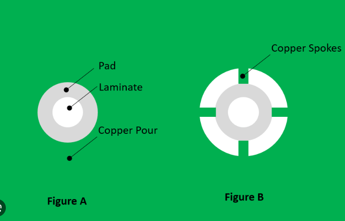
- Copper pours (solid or hatched) help distribute heat evenly.
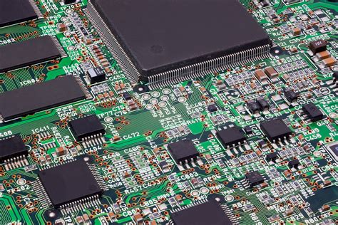
3.3 Component Placement and Layout
- High-power components should be placed away from heat-sensitive devices.
- Natural convection can be enhanced by positioning hot components near the PCB edge or top side.
- Thermal symmetry in multilayer PCBs prevents localized hotspots.
3.4 Thermal Vias
Thermal vias are plated holes that transfer heat from surface components to inner layers or heatsinks. Best practices include:
- Using multiple vias in parallel to reduce thermal resistance.
- Filling vias with thermally conductive epoxy for better heat transfer.
- Placing vias under high-power components (e.g., QFN, BGA packages).
3.5 Heat Sinks and Thermal Interface Materials (TIMs)
- Heat sinks (aluminum or copper) attached to high-power ICs (e.g., CPUs, MOSFETs) improve heat dissipation.
- Thermal pads, pastes, or adhesives enhance heat transfer between components and heatsinks.
- Active cooling (fans, liquid cooling) may be required for extreme thermal loads.
3.6 Simulation and Analysis Tools
Thermal simulation software (e.g., Ansys Icepak, FloTHERM, SolidWorks Flow Simulation) helps predict hotspots and optimize designs before manufacturing.
4. Advanced PCB Thermal Design Techniques
4.1 Embedded Heat Spreaders
- Copper or graphite layers embedded within the PCB distribute heat efficiently.
- Used in high-density designs where surface cooling is insufficient.
4.2 Two-Phase Cooling (Heat Pipes, Vapor Chambers)
- Heat pipes transfer heat via phase change (liquid-vapor-liquid cycle).
- Vapor chambers provide uniform cooling for large PCBs.
4.3 Dynamic Thermal Management (DTM)
- Adjusts power consumption based on temperature (e.g., CPU throttling).
- Prevents overheating without external cooling solutions.
4.4 3D-Printed Cooling Structures
- Additive manufacturing allows custom heat sinks and airflow channels.
5. Case Study: Optimizing a High-Power LED PCB
Problem: A high-power LED array experiences thermal throttling, reducing brightness.
Solution:
- Switched from FR-4 to aluminum-core PCB.
- Added thermal vias under LED chips.
- Used copper pours for heat spreading.
- Integrated a heat sink with thermal paste.
Result:
- Temperature reduced by 35%.
- LED lifespan increased by 50%.
6. Conclusion
Effective PCB thermal design optimization requires a combination of material selection, layout strategies, and advanced cooling techniques. By leveraging thermal vias, heat sinks, simulation tools, and innovative cooling methods, engineers can mitigate overheating risks and enhance product reliability.
As electronics continue to evolve, thermal management will remain a critical aspect of PCB design, ensuring performance and durability in demanding applications.